Power supply requirements, Antenna considerations, Helpful application notes from linx – Linx Technologies TRM-915-DTS User Manual
Page 18
– –
– –
30
31
Helpful Application Notes from Linx
It is not the intention of this manual to address in depth many of the issues
that should be considered to ensure that the modules function correctly
and deliver the maximum possible performance. We recommend reading
the application notes listed in Figure 43 which address in depth key areas
of RF design and application of Linx products. These applications notes
are available online at www.linxtechnologies.com or by contacting the Linx
literature department.
Power Supply Requirements
The module does not have an internal
voltage regulator, therefore it requires a clean,
well-regulated power source. The power supply
noise should be less than 20mV. Power supply
noise can significantly affect the module’s
performance, so providing a clean power supply
for the module should be a high priority during
design.
A 10
Ω resistor in series with the supply followed by a 10µF tantalum
capacitor from V
cc
to ground helps in cases where the quality of supply
power is poor (Figure 41). This filter should be placed close to the module’s
supply lines. These values may need to be adjusted depending on the
noise present on the supply line.
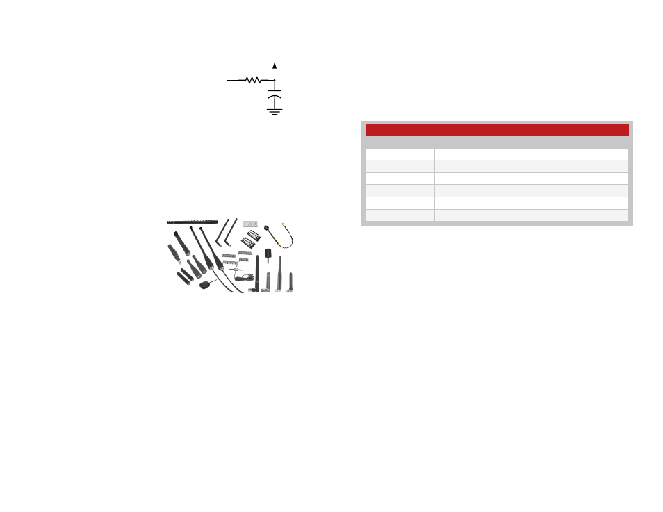
Antenna Considerations
The choice of antennas is a
critical and often overlooked
design consideration. The range,
performance and legality of an RF
link are critically dependent upon the
antenna. While adequate antenna
performance can often be obtained
by trial and error methods, antenna
design and matching is a complex
task. Professionally designed antennas such as those from Linx (Figure
42) help ensure maximum performance and FCC and other regulatory
compliance.
Linx transmitter modules typically have an output power that is higher
than the legal limits. This allows the designer to use an inefficient antenna
such as a loop trace or helical to meet size, cost or cosmetic requirements
and still achieve full legal output power for maximum range. If an efficient
antenna is used, then some attenuation of the output power will likely be
needed.
It is usually best to utilize a basic quarter-wave whip until your prototype
product is operating satisfactorily. Other antennas can then be evaluated
based on the cost, size and cosmetic requirements of the product.
Additional details are in Application Note AN-00500.
+
10
Ω
10
µF
Vcc IN
Vcc TO
MODULE
Figure 41: Supply Filter
Figure 42: Linx Antennas
Helpful Application Note Titles
Note Number
Note Title
AN-00100
RF 101: Information for the RF Challenged
AN-00126
Considerations for Operation Within the 902–928MHz Band
AN-00130
Modulation Techniques for Low-Cost RF Data Links
AN-00140
The FCC Road: Part 15 from Concept to Approval
AN-00500
Antennas: Design, Application, Performance
AN-00501
Understanding Antenna Specifications and Operation
Figure 43: Helpful Application Note Titles