Pin descriptions, Pin assignments, Pin # name description – Linx Technologies RXM-900-HP3-xxx User Manual
Page 3
Page 4
Page 5
50-ohm RF Input
Analog Ground
No Connection
ANT
GND
Channel Select 0
CS0
Channel Select 1 /
Serial Select Clock
CS1 /
SS CLOCK
Channel Select 2 /
Serial Select Data
Received Signal
Strength Indicator
Mode Select
Voltage Input 2.8-13V
1V
P-P
Analog Output
Digital Data Output
NC
Power Down
(Active Low)
CS2 /
SS DATA
PDN
RSSI
MODE
V
CC
AUDIO
DATA
SMD Only
No Connection
NC
PDN
470k
V
CC
4.7k
RSSI
V
CC
RF In
50
Ω
CS2
25k
µ
25k
µ
CS1
25k
µ
CS0
25k
µ
1
2-8
9
10
11
12
13
14
15
16
17
18
19-36
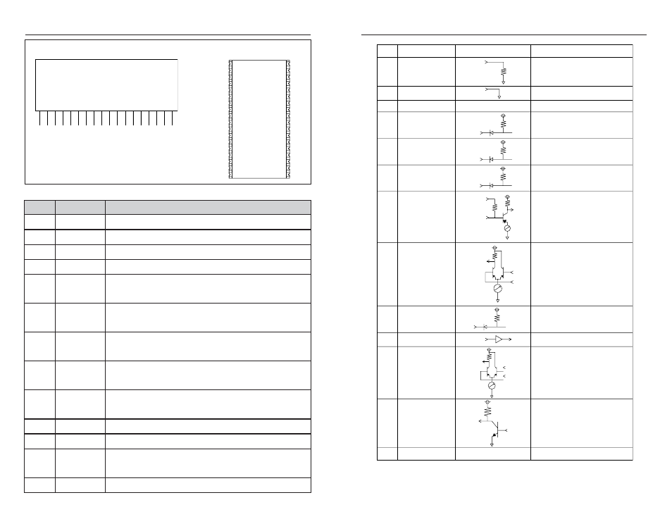
Pin #
Name
Equivalent Circuit
Description
PIN DESCRIPTIONS
Figure 8: Pin Functions and Equivalent Circuits
PIN ASSIGNMENTS
ANT
GND
GND
GND
GND
GND
GND
GND
N/C
CS0
CS1 / SS CLOCK
CS2 / SS DATA
PDN
RSSI
MODE
VCC
AUDIO
DATA
1
2
3
4
5
6
7
8
9
10
11
12
13
14
15
16
17
18
ANT
GND
GND
NC
NC
NC
NC
NC
NC
GND
GND
GND
GND
GND
NC
NC
1
2
3
4
5
6
7
8
29
30
31
32
33
34
35
36
NC
CS0
CS1 / SS CLOCK
NC
NC
NC
NC
CS2 / SS DATA
PDN
RSSI
NC
NC
9
10
11
12
13
14
23
24
25
26
27
28
MODE
VCC
AUDIO
NC
NC
DATA
NC
NC
15
16
17
18
19
20
21
22
Figure 7: HP3 Series Receiver Pinout
Pin #
Name
Description
1
ANT
50-ohm RF Input
2-8
GND
Analog Ground
9
NC
No Connection
10
CS0
Channel Select 0
11
CS1 / SS
CLOCK
Channel Select 1 / Serial Select Clock. Channel Select 1
when in parallel channel selection mode, clock input for
serial channel selection mode.
12
CS2 / SS
DATA
Channel Select 1 / Serial Select Data. Channel Select 2
when in parallel channel selection mode, data input for
serial channel selection mode.
13
PDN
Power Down. Pulling this line low will place the receiver
into a low-current state. The module will not be able to
receive a signal in this state.
14
RSSI
Received Signal Strength Indicator. This line will supply an
analog voltage that is proportional to the strength of the
received signal.
15
MODE
Mode Select. GND for parallel channel selection, V
CC
for
serial channel selection
16
V
CC
Supply Voltage
17
AUDIO
Recovered Analog Output
18
DATA
Digital Data Output. This line will output the demodulated
digital data.
19-36
NC
No Connection (SMD only)
Surface-Mount Receiver
Pinned Receiver