Troubleshooting, The prototyping area, The rf area – Linx Technologies MDEV-LICAL-MT User Manual
Page 5
–
–
–
–
4
5
The Prototyping Area
The prototyping area contains
an area of plated through holes
so that external circuitry can
be placed on the board. This
circuitry can be interfaced with the
transcoder through the breakout
header to the right. At the bottom
is a row connected to the 3V
power supply and at the top is a
row connected to ground.
All of the status lines are
connected to a wire-wrap header
to the right, allowing easy access
from the prototyping area. The
TR_DATA, TR_SEL, TR_PDN and
CONFIRM lines are also available
on the header. This allows complete control of the entire system from the
prototyping area.
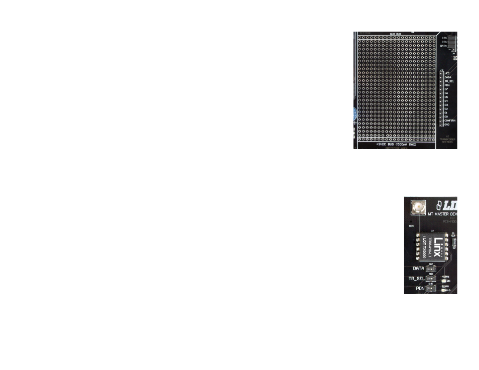
The RF Area
This board uses the LT Series transceiver for the
wireless link. R1 is connected to the LADJ line
of the transceiver to reduce the output power to
the approximate limit of Part 15.231 of the FCC
regulations. For applications where Part 15 limits are
not applicable or output levels can be legally raised,
R1 can be changed according to the graph in the LT
Series Transceiver Data Guide.
The three switches below the transceiver connect
the TR_DATA, TR_SEL and TR_PDN lines to either
the transceiver or the header in the Prototyping Area.
This prevents collisions on the lines resulting from
connecting the transcoder, transceiver, and external
circuitry to the same lines. If the switches are to the
left, then the transcoder is connected to the header; if they are to the right,
the transcoder is connected to the transceiver. Pads have been placed for
LEDs to indicate the states of the TR_SEL and PDN lines. These indicators
can be useful for debugging during development, but have been left to the
user to populate if desired.
Troubleshooting
If the boards fail to work out of the box, then try the following:
• Check the battery to make sure it is not dead
• Check to make sure that the USB interface jumpers are removed
• Make sure that the baud rate switches are set the same on both
boards. Note that the LT Series transceiver on the board can only
operate at 9,600bps.
• Make sure that the antenna is connected and has the correct polarity
connector.
• Make sure that the status lines are set correctly. The transcoder does
not activate a status line if it has been set as an input, so a status
line that is an input on one board needs to be an output on the other
board.
• Make sure that you set your Control Permissions correctly. If you have
not set the transcoder to use a particular line, then when you press
that line's button on one board, the MODE_IND LED on the other
board lights up, but the status line LED does not light up.
• Make sure that any advanced features that may have been activated
through the included software are set correctly. For example, if
Targeted Device Addressing has been enabled, then only the
transcoder with the correct address responds. These features may
need to be disabled to allow manual operation. The advanced features
are controlled through the Serial Interface Engine and can be accessed
with the included software.
If all of these appear to be in order, then call +1 800 736 6677 or email
[email protected] for technical support.
Figure 4: The Prototyping Area
Figure 5: The RF Area