The decoder board – Linx Technologies MDEV-LICAL-HS User Manual
Page 8
–
–
–
–
10
11
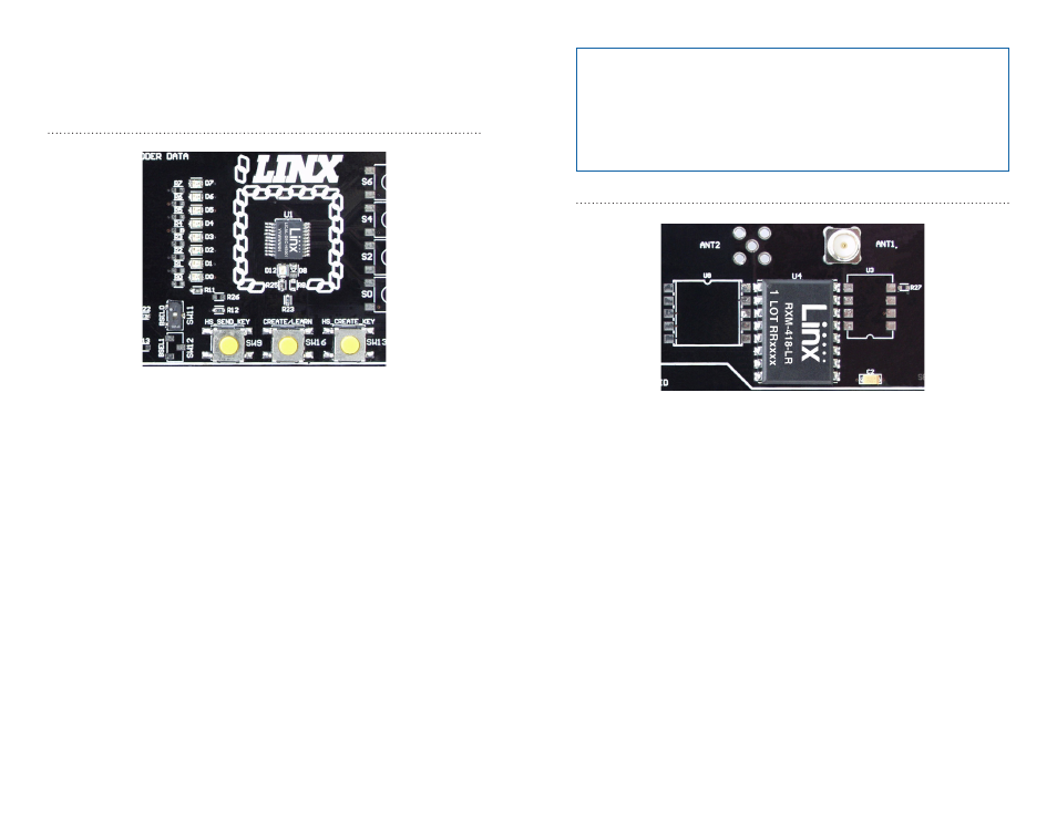
The Decoder Board RF Area
Figure 12 below shows the RF area of the development board.
This board can be populated with either the LR Series receiver (as shown)
or the ES Series receiver. Both modules can be placed on the same pads
in the center of the section, but the ANT1 connector is populated for the
LR receiver and the ANT2 connector is populated for the ES receiver.
The Decoder Board
The decoder board has four main sections of interest: the decoder area,
the receiver area, the USB area, and the key exchange area.
The Decoder Area
Figure 11 shows the decoder area of the development board.
The decoder is placed in the center beneath the Linx logo. To the left are
LEDs that are connected to the decoder data lines. These light up when
the decoder receives a signal from the encoder to take the data line high.
LED D0 corresponds to data line D0 and so forth.
Beneath the decoder is an LED that is connected to the MODE_IND line.
This lights up as described in the HS Series Decoder Data Guide.
Beneath the LED are three buttons. The one on the left labeled HS_SEND_
KEY is connected to the SEND_COPY line on the decoder. The one in
the middle is connected to the LEARN line, and the one on the right is
connected to the CREATE_KEY line. The HS_SEND_KEY button causes
the decoder to begin sending a copy of its User Data when pressed at the
same time as the LEARN button. The LEARN button is used to set Control
Permissions and, with the other two buttons, to make the decoder enter
special modes. The CREATE_KEY button causes the decoder to create a
new key when pressed at the same time as the LEARN button. All of these
functions are described in detail in the HS Series Decoder Data Guide.
There is one function switch to the left of the CREATE button. BSEL0 is
used to set the baud rate of the decoder as described in Figure 7.
Figure 11: The Decoder Area
Figure 12: The Decoder Board RF Area
Note:
The encoder board must be set to the same baud rate in order
for the signal to be received correctly. The maximum baud rate for the
LR Series is 10,000bps, so only 4,800bps can be used on boards
populated with these modules. The ES Series receiver can use both
baud rates. If the switch is up, then the line is high, if it is down, then
the line is low.