Ordering information, Mdev-usb-qs development board, Getting started – Linx Technologies MDEV-USB-QS User Manual
Page 4: The usb area
–
–
–
–
2
3
Getting Started
There are four areas on the development board: the USB area, the RS-232
area, the Microcontroller area and the Prototyping area. The RS-232 area
connects the QS module to a standard DB9 serial connector through a
RS-232 level converter chip. This section allows for full handshaking so
that a legacy device can be connected and tested. The microcontroller
section connects the QS to a Microchip PIC microcontroller. The included
software demonstrates how to interface the QS to the PIC for bi-directional
communication with a custom processor. Much of the source code is
documented in the software’s help file.
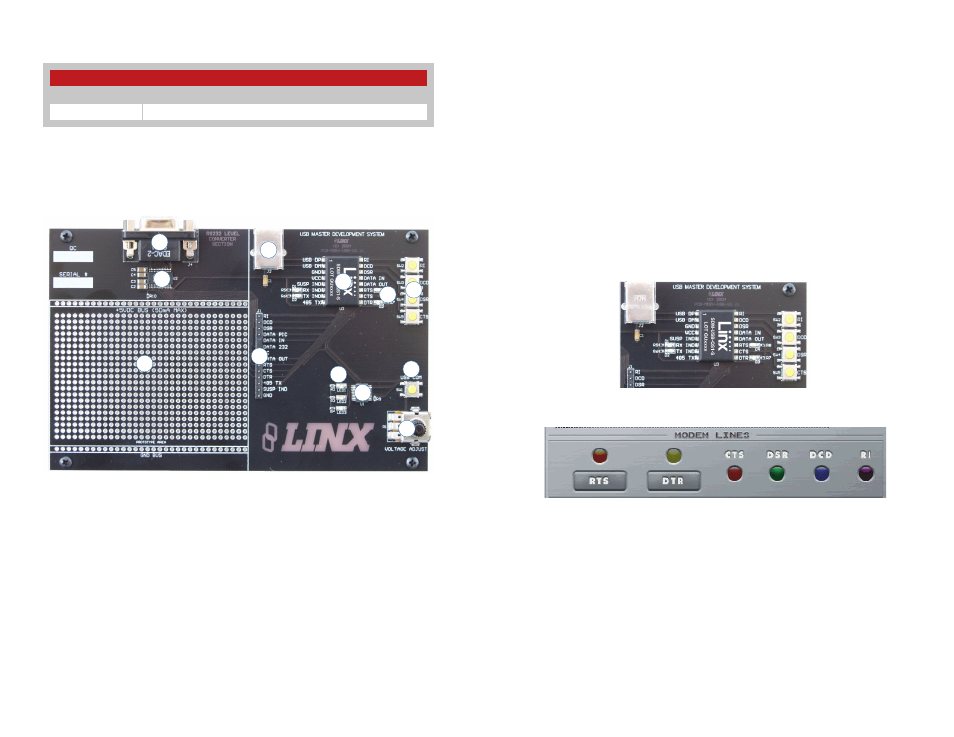
The USB Area
This section demonstrates how to activate the modem outputs and read
the modem inputs. Figure 4 shows the development board and Figure 5
shows the Modem Line section in the development software.
Pressing the RTS and DTR buttons in the software activates the RTS and
DTR LEDs on the development board. Pressing the RI, DCD, DSR or CTS
buttons on the board causes the appropriate indicator on the software
screen to light up. The source code for this is in the software’s Help File.
There are two LEDs to the left of the module, one marked TX IND and
another marked RX IND. These flash when the module is sending and
receiving data, respectively.
Note that the modem lines are designed to work with UARTs, so the states
are inverted. The lines are at V
CC
when off and at ground when on.
MDEV-USB-QS Development Board
1. DB9 Connector
2. RS-232 Level Converter Chip
3. Prototyping Area
4. Breakout Header
5. USB Jack
6. QS Module
7. Modem Line Buttons
8. Modem Line LEDs
9. Microcontroller
10. Microcontroller LEDs
11. Microcontroller Button
12. Voltage Adjust Potentiometer
Figure 4: The USB Area
Figure 5: Development Software Modem Line Section
Ordering Information
Ordering Information
Part Number
Description
MDEV-USB-QS
QS Series Master Development Kit
Figure 2: Ordering Information
1
2
3
4
5
6
7
8
9
10
11
12
Figure 3: The QS Series Development Board