The prototyping area, Installing the software and drivers – Linx Technologies MDEV-USB-QS User Manual
Page 6
–
–
–
–
6
7
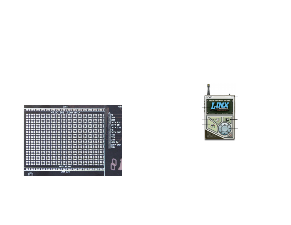
The Prototyping Area
The prototyping area contains an area of plated through holes so that
external circuitry can be placed on the board. This circuitry can be
interfaced with the QS module through the breakout header to the right.
At the bottom of this area is a row connected to ground and at the top is a
row connected to the USB power supply. The circuitry on the development
board draws approximately 40 to 50mA of current, so any circuitry added
to the prototyping area cannot draw more than 50mA before enumeration,
per the USB specification (please see the Power Supply Guidelines in the
module’s data guide for more information). If the circuitry requires more
current, then an external power supply is required.Resistor R10 is a 0-ohm
jumper that can be removed to isolate the power supply row from the USB
supply so that an external supply can be attached to this row.
All of the module’s control and data lines are connected to the header,
allowing easy access from the prototyping area. A jumper is also included
to route the data from the RS-232 Section or the Microcontroller section to
the QS module. It must be appropriately set before the sections will work
properly.
Figure 9: The Prototyping Area
Installing the Software and Drivers
The software included with the Master Development System uses the
Direct Drivers and cannot be used with the Virtual COM Port Drivers. Both
drivers are included on the CD with the software, so be sure to choose the
appropriate one.
The first time a QS module is plugged into a computer, Windows displays
the Found New Hardware Wizard, which guides the installation of the
drivers. Application Note AN-00201 “Installing the SDM-USB-QS-S Drivers”
describes the installation of the drivers in detail. The drivers should be
installed before running the Development Software.
The QS Series Master Development System Software automatically starts
when the CD is inserted and the player in the figure below appears.
Clicking the Install Software button starts the Installation Wizard,
which guides the installation of the development software. The View
Documentation button shows a list of the application notes and manuals
related to the QS module. Selecting one of these opens the file in Adobe
Acrobat. The Play Movie button plays a short video about Linx in the
Player screen, which can be controlled with the Selection Keypad. Clicking
the button on the bottom right of the player opens the Linx Technologies
homepage in the computer’s default browser.
Options listed in the View Documentation list allow for the installation of
Adobe Acrobat Reader so that the documents may be viewed. There is
also the option of installing Flash, which may be required if the Linx video
does not play correctly.
Install Software
View Documentation
Play Movie
Exit
Go To The
Linx Homepage
Selection Keypad
Player Screen
Figure 10: Software Installer