Input interpretation selection switches, Selecting the protocol, Development using the prototyping area – Linx Technologies OEM Transmitter Evaluation Kit User Manual
Page 6: Using the boards as a design reference
–
–
–
–
6
7
Development Using the Prototyping Area
In addition to evaluation functions, the boards may also be used for
product development. The evaluation board features a prototyping area for
the addition of application-specific circuitry. This area has connections to
V
CC
at the top and to ground at the bottom that can be used to power any
circuitry that is added.
The holes are plated and set at 0.1" on center with a 0.04" diameter,
accommodating industry-standard SIP and DIP packages. The data line
outputs, Valid Transmission (VT) and the DATA line from the receiver (DIN)
have been wired out to a header row to the right of the prototyping area.
This allows easy access for connection to external circuitry. Data line D0 is
connected to a buzzer, D1 to D7 and VT are connected to LEDs.
Using the Boards as a Design Reference
Since the OEM transmitters are a finished product, most of the designer’s
work will be incorporating the receiver into the end product. The basic
evaluation board included in this kit is very simple, yet illustrates some
important techniques that should be incorporated into the board layout.
The receiver’s mounting pads extend slightly past the edge of the part. This
eases hand assembly and allows for better heat conduction under the part
if rework is necessary. A full ground plane fill is placed on the bottom of the
board. This ground plane serves three important purposes:
First, since a quarter-wave antenna is employed, the ground plane is
critical to serve as a counterpoise (please see Application Note AN-00500
“Antennas: Design, Application, and Performance” for details on how a
ground plane affects antenna function).
Second, a ground plane suppresses the transfer of noise between stages
of a product as well as unintentional radiation of noise into free space.
Third, a ground plane allows for the implementation of a microstrip feed
between the module and the antenna. The term microstrip refers to a PCB
trace running over a ground plane that is designed to serve as a 50-ohm
transmission line. See the LR Series receiver data guide or the calculator
available on our website for details on microstrip calculations.
Note:
If added circuitry requires a higher current than can be provided
by the batteries, the batteries must be removed and the board
powered from an external source.
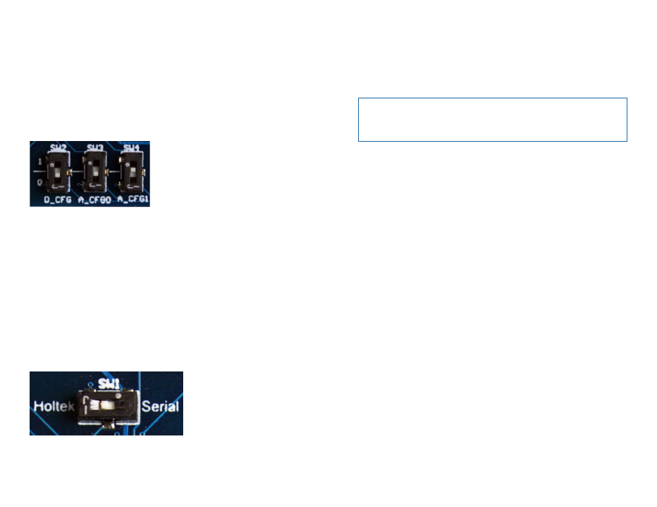
Input Interpretation Selection Switches
The DS Series was designed to replace an encoder and decoder from
Holtek. These parts had tri-state lines, so the address and data lines could
be high, low or floating. The DS can only be high or low, so these selection
switches are included for backwards compatibility. In the case of the OEM
transmitters, the switches should be set as follows: D_CFG to 0 or down,
A_CFG0 to 0 or down and A_CFG1 to 1 or up (Figure 5). These lines are
hardwired in the transmitter so must be set on the receiver board to match.
Please see the DS Series data guide for more information on the input line
interpretation.
Selecting the Protocol
The DS Series encoder / decoder offers two over-the-air protocols:
Holtek and serial. The Holtek selection is used when communicating with
other Holtek devices. This is a legacy protocol that provides backwards
compatibility.
The serial selection offers a much more reliable protocol that offers better
range and response time. The protocol is selected by a switch on the
HHPC and HHLR transmitter and the Protocol Select Switch on the
evaluation board, as shown in Figure 6. The CMD-Key# transmitter does
not support serial protocol. The protocols are not interoperable, so the
switches must be set the same on both sides.
Figure 5: The Evaluation Board Input Interpretation Selection Switches
Figure 6: The Evaluation Board Protocol Selection Switch