The decoder board – Linx Technologies MDEV-xxx-HH-CP8-MS User Manual
Page 6
–
–
–
–
6
7
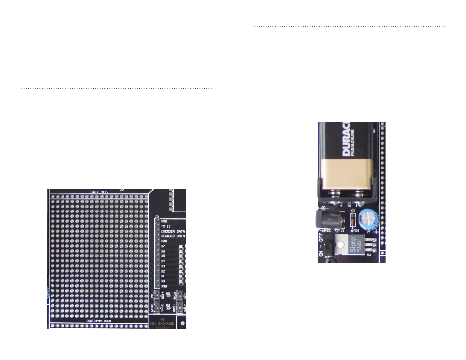
The Power Supply
The power supply on the decoder board consists of a 9V battery
and power jack connected to a 3.0V voltage regulator. It can provide
approximately 500mA of current to the prototyping area, so if the added
circuitry will need more than this, the designer must add an external supply.
If the circuit consistently draws more than 100mA of current, it might be
better to use the power jack rather than the battery, as the battery may run
down fairly quickly, reducing testing and development time.
The jack accepts a standard 5.5mm plug with the tip ground and the outer
shell 7 to 16VDC positive supply. While a reverse voltage protection diode
has been included on the board to protect the circuitry in case the voltage
on the plug is reversed, it is still a good idea to double-check the polarity.
Figure 9: The Decoder Board Power Supply Area
The Decoder Board
The decoder board included with the evaluation kit uses an LR Series
receiver to receive the signal from the Handheld transmitter and then
feeds it into an MS Series decoder. The board is designed to allow full
access to the many features of the decoder and to speed development
and integration of the LR and MS into a product. The following sections
describe the features of this board in detail.
The Prototyping Area
The prototyping area on the decoder board contains a large section of
plated through-holes so that external circuitry can be placed on the board.
This circuitry can be interfaced with the MS Series decoder through the
breakout header to the right of the holes. At the bottom of this area is a row
connected to the 3V power supply and at the top is a row connected to
ground.
All of the data lines are connected to a wire-wrap header to the right,
allowing easy access from the prototyping area. The Decoder Data and
TX ID lines are also available on the header as well as the PDN line from
the RF module. This allows complete control of the entire system from the
prototyping area, giving the designer a great deal of flexibility in using the
board.
Figure 8: The Decoder Board Prototyping Area