Linx Technologies MDEV-xxx-HH-CP8-HS User Manual
Page 9
–
–
–
–
12
13
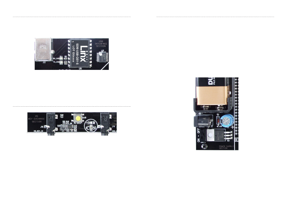
The Decoder Board USB Area
The decoder development board has a Linx SDM-USB-QS-S module for
use with the included development software. This module is powered by
the USB bus, so it does not pull any current from the battery. Figure 12
shows the USB area on the decoder board.
The microcontroller on the right monitors the decoder data lines and
generates commands that are sent to the development software on the PC
via the QS Series USB module. The RX_IND LED to the left of the module
flashes to indicate that data is being received from the microcontroller.
The Decoder Board Key Exchange Area
Figure 13 shows the key exchange area of the development board.
The key is created in the decoder and transferred to the transmitter with an
infrared (IR) link. This consists of an infrared diode (IR2) that is modulated
by the KEY_OUT line of the decoder and an infrared receiver built into
the transmitter. Once the key is created, the decoder outputs the key
information through this circuit. The clear plastic window on the back of
the transmitter should be held within a few inches of the infrared diode
and the key transfer happens automatically. Jack J4 is also connected
to the KEY_OUT line and is available for wired transfer of the key, but the
handheld transmitter is not adapted to accept a wired connection. The rest
of the circuitry is used for sending and receiving copies of the decoder’s
User Data, as described in the HS Series Decoder Data Guide, but is not
required for operation of this development system.
The Power Supply
The power supply consists of a 9V battery and a power jack connected to
a 3.0V voltage regulator. The regulator can provide approximately 500mA of
current to the prototyping area. If the added circuitry needs more than this,
then an external supply must be added. If the circuit consistently draws
more than 100mA of current, it might be better to use the power jack, as
the battery will run down fairly quickly, reducing testing and development
time.
The jack accepts a standard 5.5mm plug with the tip ground and the outer
shell 7 to 16VDC positive supply. A reverse voltage protection diode has
been included on the board to protect the circuitry in case the voltage on
the plug is reversed, but it is still a good idea to double-check the polarity.
Figure 13: The Decoder Board Key Exchange Area
Figure 12: The Decoder Board USB Area
Figure 14: The Power Supply Area