Magnum Energy DC Breakers (BR-DC) User Manual
Magnum Energy Equipment
High Capacity DC Breakers Instruction Sheet
Part Number: 64-0040 Rev B
1
Magnum Energy, Inc.
2211 West Casino Rd.
Everett, WA 98204
www.magnumenergy.com
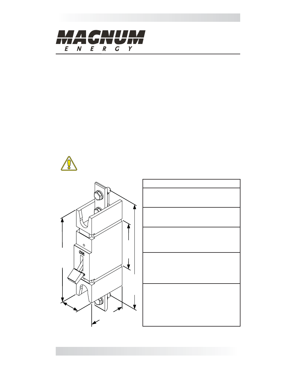
Figure 1, Physical Dimensions
7.
12
5
(180
.9
7)
8.
334
(21
1.
68)
3.
82
8
(9
7.
23)
2.968
(75.39)
1.5
(38.1)
Introduction
The BR-DC175 and BR-DC250 are the same DC breakers installed in the MP
(Magnum Panel) and MMP (Mini Magnum Panel) system enclosures, and in-
cluded with the MPX extensions. These breakers function as the inverter’s DC
disconnect switch and can be used as the battery-to-inverter circuit protection
in most installations. These breakers were specifi cally designed and tested to
work with Magnum inverters to provide the delay time needed to minimize
nuisance breaker tripping.
Depending on the part number, the circuit breaker is either a 175 amp (PN:
BR-DC175) or a 250 amp (PN: BR-DC250), high interruption capacity, mag-
netic-hydraulic, DC circuit breaker. These breakers have front-accessible con-
nections, each provided with a 3/8-16 captive nut. Each breaker includes two
3/8-16 Hex head bolts with washers, and a back mount kit for installing this
breaker inside MP enclosures. This kit consists of two mounting straps and two
#10-32 x 3.5” Torx screws to attach the DC breaker to a mounting panel.
CAUTION: These breakers must be mounted in a vertical position
to meet the specifi ed trip current and trip delay curve.
Specifi cations
Approvals
UL 489 Listed Branch Circuit-Breaker
CSA Certifi ed C22.2 No. 5
•
•
Interrupting Capacity
10,000 amperes at 160VDC
65,000 amperes at 65VDC
•
•
Trip Time Delay
Customized Delay 53 (DC long delay),
constructed to work specifi cally with
Magnum inverters.
Recommended Torque:
220 - 230 inch-pounds (using 3/8”
bolts to connect cables - having ring
lug terminals - to the 3/8-16 captive
nuts on the copper extensions).
Physical:
Weight: ~2.25 lbs. (1020 grams)
Size: See Figure 1
Terminal connections: Two Front-
accessible, tinned-copper extensions,
each with a 3/8-16 x 1” bolt and
washer screwed into a captive nut.
•
•
•
Sizes shown in
inches (mm)