Side panel diagram – Curtis RLC2609 User Manual
Page 6
Advertising
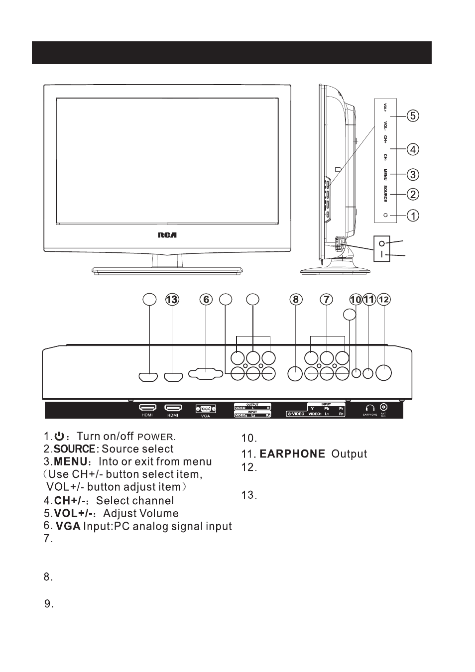
Side panel diagram
5
POWER SWITCH
14
16
15
9
14/15.
VIDEO/R/L
:
1/2
external AV
signal input and relevant right/left
sound channel.
VGA/AUDIO: VGA audio input.
ANT 75 ohm: Connect the antenna to
the antenna input.
HDMI1 Input: Digital signal input from
HDMI video connector
S-VIDEO: Color and brightness
difference components input.
YPbPr
:Color difference
components input and relevant
video input
AV Output
16. HDMI2 Input
(3.5mm)
PC
AUDIO
INPUT
2
1
ON
OFF
Advertising