Instructions for use 3. specification, Fig.1 fig.2, Fig.4 fig.3 – Sealey PWH620 User Manual
Page 2
WARNING! Before using the helmet for welding ensure you
have read and understood the safety instructions in Section 1.
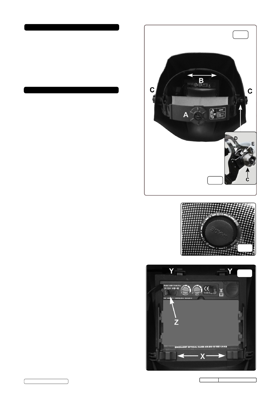
4.1 Assemble the headband parts (see fig.1) into the mask as
indicated in fig.2. Before the mask can be used the
headband must be adjusted to fit the user properly.
4.2 ADJUSTING THE FIT OF THE HELMET.
The overall circumference of the headband can be made
larger or smaller by pushing in and rotating the knob on the
back of the headband (See adjustment ‘A’ in fig.1). This
can be done whilst wearing the helmet and allows just the
right tension to be set to keep the helmet firmly on the
head without it being too tight.
4.3 If the headband is riding too high or too low on your head
adjust the strap which passes over the top of your head. To
do this release the end of the band by pushing the locking
pip out of the hole in the band. Slide the two portions of the
band to a greater or lesser width as required and push the
locking pip through the nearest hole (See adjustment ‘B’ in
fig.1).
4.4 Test the fit of the headband by lifting up and closing down
the helmet a few times whilst wearing it. If the headband
moves whilst tilting re-adjust it until it is stable.
4.5 ADJUSTING HELMET TILT.
If the cartridge window is not aligned with the eyes when
the helmet is in the lowered position adjust the tilt of the
helmet in relation to the headband. Referring to fig.2 loosen
the knob ‘C’ adjacent to the tilt plate ‘D’. Lift the tilt lever
‘E’off tilt plate ‘D’ and rotate it to the required position
Retighten the clamp knob ‘C’.
4.6 SELECTING SHADE LEVEL
4.6.1 Refer to the shade guide in Section 7. Select setting 5-8 or
9-13 on the back of the cartridge (see fig.4 ‘Z’) and adjust
the knob on the side of the helmet to the correct setting
(fig.3).
4.7 GRIND POSITION. Turn the shade knob (fig.3)
anti-clockwise until it clicks into the grind position.
When
grinding is finished the knob must be turned back to the
appropriate shade position before welding again.
Failure to
do this could result in damage to your eyes.
4.8 SELECTING DELAY TIME/RESPONSE TIME
4.8.1 The delay time in which it takes the lens to change from
dark to light or vice versa can be varied from 0.1sec to 0.9
sec, this adjustment is carried out by turning the delay time
knob on the inside of the cartridge, see fig.4.
4.9 SENSITIVITY
4.9.1 For normal ambient light conditions set the sensitivity knob
to the high setting (fig.4).
4.9.2 For conditions where there is an excess of light, which may
affect the performance of the lens, turn the knob to the low
setting.
4. INSTRUCTIONS FOR USE
3. SPECIFICATION
Original Language Version
PWH620 Issue No.1 13/05/13
fig.1
fig.2
Model No: ...........................................PWH620
Shade Active: ......................................5-8 or 9-13 Variable
Shade Inactive:....................................4
Viewing Area: ......................................100 x 53mm
Grinding Function: ...............................YES
Operating time, Light/Dark: .................< 0.1ms
OperatingTemperature: .......................-10°C to +60°C
Power: .................................................Solar Cells
Weight:.................................................550g
© Jack Sealey Limited
fig.4
fig.3