Fig.1 fig.2, Assembly – Sealey SPB57W User Manual
Page 2
Original Language Version
sPB57W Issue: 1 - 17/06/11
fig.1
fig.2
4. AssEMBLY
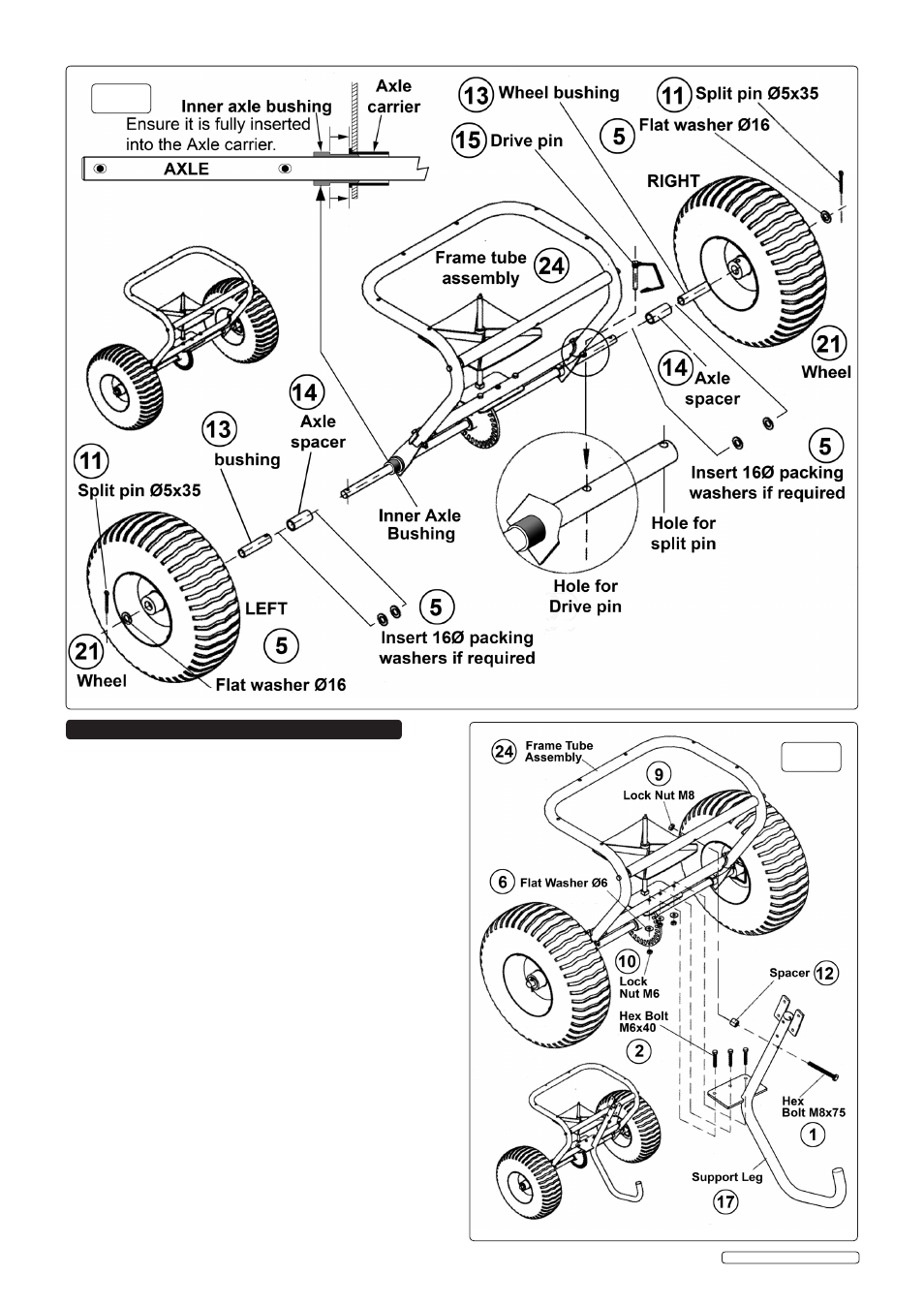
4.1 AssEMBLING THE wHEELs. (refer to fig.1)
please note that the left hand wheel turns freely on the
axle whilst the right hand wheel is pinned to the axle and
thus drives the central gearwheel.
4.1.1 Before commencing assembly, ensure that the black plastic
inner axle bushing is fully inserted into the black plastic axle
carrier on both sides of the axle. see fig.1.
4.1.2 slide an axle spacer (14), followed by a wheel bushing (13)
onto the left hand side of the axle.
4.1.3 slide a wheel (21) onto the wheel bushing (13).
4.1.4 Place a flat washer Ø16mm (5) over the end of the axle and
insert a spilt pin Ø5x35mm (11) through the hole in the end of
the axle. If there is excessive play between the components
there are two extra washers (5) available to pack out the
assembly if required. see fig.1. When the wheel runs easily
without excessive play, bend over the ends of the split pin (11)
to retain the assembly.
4.1.5 slide an axle spacer (14) onto the right hand end of the axle
followed by a wheel bushing (13). Ensure that the holes in the
end of the wheel bushing are nearest to the spacer and align
with the hole in the axle.
4.1.6 slide a wheel (21) onto the wheel bushing (13) and align the
holes in the inner wheel hub with the holes in the wheel bushing
and the axle.
4.1.7 undo the clip on the drive pin (15) and insert it through all three
components. close the clip on the drive pin.
4.1.8 Place a flat washer Ø16mm (5) over the end of the axle and
insert a spilt pin Ø5x35mm (11) through the hole in the end of
the axle. Bend over the ends of the split pin (11) to retain the
assembly.
4.2 AssEMBLING THE sUppORT LEG. (refer to fig.2)
4.2.1 Position the support leg (17) so that the leg extension is
pointing away from the wheel assembly.
4.2.2 the support leg mounting plate and the gear shaft mounting