Fig.3 fig.4 – Sealey SPB57W User Manual
Page 3
Original Language Version
sPB57W Issue: 1 - 17/06/11
fig.3
fig.4
plate rest on either side of the same cross brace nearest to the
axle and are fixed in place with three M6 x 40mm Hex bolts (2)
together with three M6 lock nuts (10) and three flat washers
Ø6mm (6). remove any bolts that may be retaining the gear
shaft mounting plate and align the holes in the support leg
mounting plate with the three holes in the cross brace. Insert
the three retaining bolts through the cross brace and both
plates and retain with the lock nuts and washers.
4.2.3 Position the metal spacer (12) between the support leg (17)
and the other cross brace and insert the M8x75mm Hex bolt
(1) through all three components. retain the assembly with an
M8 lock nut (9).
4.2.4
Do not fully tighten the fixings at this stage.
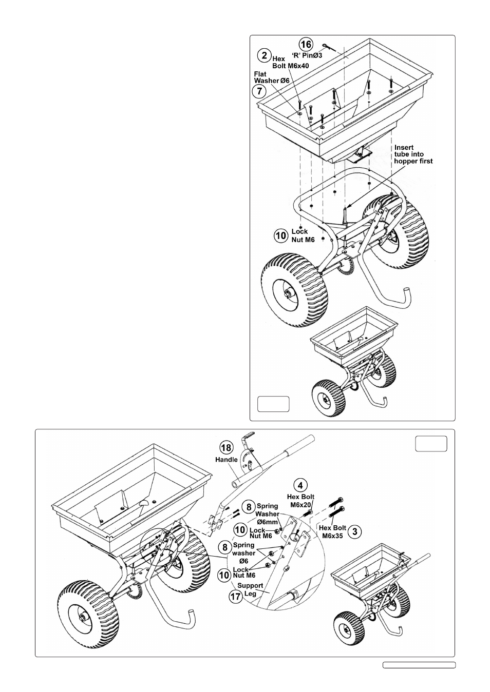
4.3 INsTALLING THE HOppER. (refer to fig.3)
4.3.1 Align the gear shaft with the hole in the black plastic moulding
on the underside of the hopper and lower the hopper onto the
shaft and onto the support frame.
4.3.2 Insert six M6x40mm hex bolts (2) together with six M6Ø
washers (7) through the hopper and support frame and secure
with six ØM6 lock nuts (10).
Do not fully tighten the fixings
at this stage.
4.3.3 Insert the 'r' pin (16) through the hole in the top of the gear shaft.
4.4 FIxING THE HANDLE TO THE sUppORT LEG. (refer to fig.4)
4.4.1 Insert the bottom of the handle tube (18) into the top of the
support leg (17) and align the two holes.
4.4.2 Insert two M6x35mm hex bolts (3) through both components
and retain with two Ø6mm spring washers (8) and two M6 Lock
nuts (10).
4.4.3 Adjust the position of the gear shaft mounting plate so that the
gear and pinion work smoothly together, then tighten the three
plate fixings and recheck the gear operation.
when the gears
operate smoothly tighten all other fixings.
4.5 CONNECTING THE FLOw CONTROL LINKAGE. (refer to fig.5)
4.5.1 connect the flow control linkage rod between the swivel plate
on the underside of the hopper and the control lever. When
holding the handle, the linkage should be on the right hand
side in order for the hopper shutter to open and close correctly.
slide a Ø8mm flat washer (6) over the end of the rod with the
more pronounced bend and insert the threaded end into the
swivel plate. Place a washer (6) over the other end and insert it
through the link on the control lever and into the small slot on
the control lever plate. check that the control lever correctly
opens and closes the hopper shutter, then retain the linkage
with an Ø8mm lock nut (9) on either end.
4.5.2 If shutter still does not fully close, loosen the two nuts that attach
the flow lever bracket to the handle and move the whole
bracket back and forth. When handle is at zero the shutter must
be fully closed. When the handle is at '30' the shutter should
be open. tighten bracket nuts when adjustment is complete.