Fig.2 fig.3 fig.4 fig.4, Fig.1, Assembly – Sealey SSB37W User Manual
Page 4
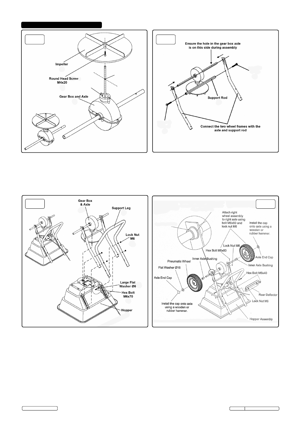
5. ASSEMBLY
5.3. Refer to fig.3 for support leg and gearbox fitting.
5 .3 .1 . Take the hopper (11) and lay it upside down, lower the gearbox and frame onto the hopper, inserting the vertical axle through the
hopper and centre hub (13) .
5 .3 .2 . on top of the wheel frame, lay the support leg (26), secure together with hex bolts M6x70 (14) and large washer (41),
Inserting from inside the hopper securing with lock nuts (25) on the outside .
5.4. Refer to fig.4 for undercarriage and rear deflector fitting.
5 .4 .1 . Slide the outer axle bushes (33) over the axle and push into the frame with location lobe innermost, see also fig .6 .
5 .4 .2 . Insert the inner axle bush (32) into the outer axle bush .
5 .4 .3 . Fit the wheels (29) . Secure the right hand wheel using hex bolt M6x60 (36) and a lock nut (25); see fig .4 and fig .6 for clarity .
5 .4 .4 . Place a flat washer (30) over the end of the axle and then the axle caps (31) . use a soft faced mallet to ensure the axle caps are seated
correctly .
5 .4 .5 . Attach the rear deflector (58) to the support leg; fasten with M6x40 hex bolts (24) and M6 lock nuts (25) .
fig.2
fig.3
fig.4
fig.4
Note! Before assembly ensure there are no missing parts or fixtures .
5.1. Refer to fig.1 for fitting the impeller.
5 .1 .1 . Slide the Impeller (19), with vanes uppermost over the vertical axle on the gearbox (34) . Align the hole in the impeller boss with the
lower pre-drilled hole in the spindle .
5 .1 .2 . Secure the Impeller to the axle with a round head screw M4x20 (35) . Ensure the impeller is secured to the lower hole on the vertical axle .
5.2. Refer to fig.2 for fitting the wheel frames (forks).
5 .2 .1 . Slide the wheel frames (27) and (18) over the axle, ensure the bush housing (33) is facing inwards as in fig .5 and fig .6 .
5 .2 .2 . Secure with support rod (47) and M6x35 hex bolts (20) .
fig.1
Flange of outer axle
bushing outermost with
the keyed lug innermost .
Inner axle bushing
and wheel spacer
outermost .
(19)
(35)
(34)
(20)
(47)
(20)
(27)
(18)
(33)
(33)
(34)
(26)
(25)
(14)
(41)
(11)
(38)
(31)
(30)
(29)
(32)
(36 & 25)
(24)
(25)
(33)
(32)
(58)
[See also fig.6
for fitting bushes]
(28)
Impeller
fixing
point
Hex Bolt
M6x35
Hex Bolt
M6x35
Original Language Version
SSB37W Issue: 2 (A) - 26/08/14
© Jack Sealey limited