Fig.8, Fig.9 fig.7, Fig.6 fig.5 – Sealey SSB37W User Manual
Page 5
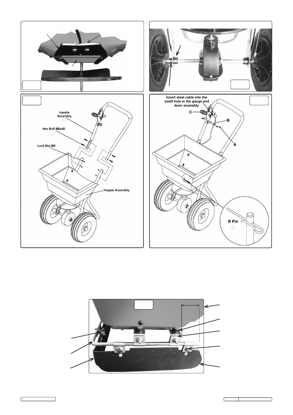
5.5. Refer to fig.7 for handle fitting.
5 .5 .1 . Turn the spreader onto its wheels and slide the handle assembly (42) around the frame, secure with 4 M6x40 hex bolts (24) and lock
nuts (25) .
5.6. Refer to fig.8 for control lever and cable fitting.
5 .6 .1 . Insert the bent end of the control cable (38) into the small hole in the lever assembly .
5 .6 .2 . Remove the hex screws (17) from the cable clamp, then insert the control cable into the clamp (A,B) .
5 .6 .3 . Re-insert hex screws to clamp control cable in place .
5 .6 .4 . Move the flow control lever (C) down to open the spreader slot in the bottom of the hopper . If the hole (fig .13) is not fully exposed or fully
closed, loosen the cable clamp (B) and adjust the cable .
5 .6 .5 . Insert R-pin (12) through top of the vertical axle .
fig.8
(35,25) Pinned hub this side
FRonT
(32)
fig.9
fig.7
5.7. Refer to fig.9 for fitting front and side deflectors.
5 .7 .1 . offer the 4-M6 X 30 screws (60) from inside the hopper and fit 4 brackets (57) to underside of hopper with spacers (9) between .
5 .7 .2 . Slide the boom rail (54) through the 1st clip in items (57) and (60), then brackets (57), finally the 2nd clip as indicated .
5 .7 .3 . Clamp all 3 deflectors with wing nuts (51) and carriage bolts (52) .
Hopper
(9), (21), (59), (60)
(57)
(52)
(54)
(51)
(53, 56 opposite)
(55)
1st
2nd
55
(33)
Impeller (19)
Hopper (11)
(16)
(43)
(37),(17),(21)
Cable (38)
fig.6
fig.5
(42)
(24)
(25)
(39)
(37) & (38)
(4) & (5) & (6)
(12)
Original Language Version
SSB37W Issue: 2 (A) - 26/08/14
© Jack Sealey limited