Fig.4 fig.5 fig.6, Fig.7 fig.8, Starting 6. operation – Sealey G1050I User Manual
Page 3
5. STARTING
6. OPERATION
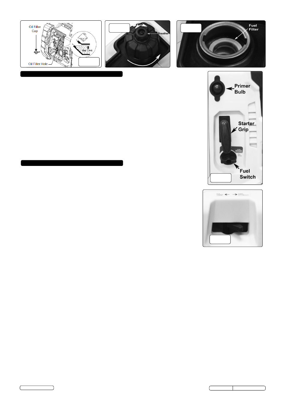
fig.4
fig.5
fig.6
5.1.
Make sure that all appliances are disconnected from the output sockets and the
generator is level before starting.
5.1.1.
Turn the fuel cap breather fully clockwise to the 'ON' position. (fig. 5)
5.1.2.
Turn the ignition switch to the 'ON' position. (fig.2 or 3).
5.1.3..
Move the choke lever to the 'START' position (fig.8).
NOTE: When the engine is hot, the
choke need not be used.
5.1.5.
On first use
prime the fuel system by pressing the primer bulb (fig.7) 25-30 times.
5.1.6.
Pull the recoil starter slowly, until you feel tension in the starter cord. Then pull the recoil
starter quickly to its full extent. Do not allow the cord to snap back; let the starter cord
rewind slowly as you hold the recoil starter handle.
5.1.7.
If engine fails to start, check that the controls are in the correct position as in 5.1.1. - 5.1.4.
above.
5.1.8.
When the engine is running smoothly, return the choke lever to the 'RUN' position.
NOTE: If the engine stops and will not restart, check the fuel and engine oil level
before troubleshooting further.
fig.7
fig.8
6.1.
SMART THROTTLE
Engine speed is kept at idle automatically when the electrical appliance is disconnected
and it returns to the proper speed to power the electrical load when electrical
appliance is connected. This position is recommended to minimize the fuel consumption
while in operation.
6.1.1.
With the switch (fig.2 or 3) in the 'ON' position, engine speed is automatically lowered
when loads are reduced, turned off or disconnected.
6.1.2.
When appliances are turned on or reconnected,the engine returns to the proper speed to
power the electrical load.
6.1.3.
In the 'OFF' position, the Smart Throttle does not operate.
6.1.4.
Appliances with large start-up power demands may not allow the engine to reach normal
operating rpm when they are connected to the generator. Turn the Smart Throttle Switch
to the' OFF' position and connect the appliance to the generator. If the engine still will not
reach normal operating speed, check that the appliance does not exceed the rated load
capacity of the generator.
6.1.5.
If high electrical loads are connected simultaneously, turn the Smart Throttle Switch to the
'OFF' position to reduce voltage changes.
6.1.6.
The Smart Throttle Switch is not effective for use with appliances that require only
momentary power. If the tool or appliance is likely to be turned on and off quickly, the
Smart Throttle Switch should be in the 'OFF' position.
6.1.7.
When using the DC output, turn the Smart Throttle Switch to the 'OFF' position.
6.2.
EARTHING
6.2.1.
Ensure that the generator is earthed when the connected equipment has an earth connection.
6.2.2.
To prevent electrical shock from faulty appliances,the generator should be earthed. Connect a length of heavy wire between the
generator’s earth terminal and an external earth source.
6.2.3.
Connections for standby power to a building’s electrical system must be made by a qualified electrician and must comply with
all applicable laws and electrical codes.
DANGER!
Improper connections can allow electrical current from the generator to back feed into the electricity supply mains. Such
back feed may electrocute utility company workers or others who contact the lines during a power outage, and when utility
power is restored, the generator may explode, ignite or cause fires in the building’s electrical system.
6.3. A.C.
APPLICATIONS
6.3.1.
Start the engine and make sure the output indicator LED (green) flashes (fig.2 or 3)
6.3.2.
Confirm that the appliance to be used is switched off, and plug in to the generator.
6.3.3.
When an electric motor is started, both the overload indicator LED (red) and the output indicator LED (green) may light
simultaneously. If the overload indicator LED (red) goes off after about four seconds, this is normal. If the overload indicator
LED (red) stays on, consult your Sealey dealer.
6.4.
D.C. BATTERY CHARGING
6.4.1.
Before connecting the battery charging cable to a battery that is installed in a vehicle, disconnect the vehicle's battery earth cable
from the negative (-) battery terminal.
6.4.2.
Connect the charging cables to the DC outlet of the generator and then to the battery terminals.
6.4.3.
Connect the red lead of the battery charging cable to the positive (+) battery terminal and the black lead to the negative (-) battery
.terminal
6.4.4
The DC circuit breaker (fig.2 or 3) automatically cuts off the DC battery charging circuit when the DC charging circuit is:
overloaded, when there is a problem with the battery, or when the connections between the battery and the generator are incorrect.
6.4.5.
The circuit breaker may be reset by pressing the red button in, once the fault has been identified and corrected.
6.4.6.
To disconnect: stop the generator, remove the black lead from the negative (-) battery terminal, remove the red lead from the positive
(+) battery terminal then remove the charging lead plug from the 12V DC socket on the control panel.
Original Language Version
© Jack Sealey Limited
G1050I, G2000I Issue: 1 - 06/06/14