Fig.6 fig.4, Fig.5 fig.7, Operation (all heaters) – Sealey EH15001 User Manual
Page 3
4.2.2. Slide a plain washer (H) over each end of the axle rod, followed
by a wheel (J) followed by anther plain washer (H).
4.2.3. Screw a nyloc nut (L) onto each end of the axle by hand until it
begins to bite. Hold one nut steady with a 19mm spanner and
progressively tighten each nut until it bottoms out on the thread.
4.3. ASSEMBLY OF THE HANDLE. (See fig.3)
4.3.1. Slide a plain washer over each of the four M5 x 50mm bolts
supplied.
4.3.2. Lay the 'U' shaped handle frame onto the front face of the leg
frames and align the two holes at each end of the handle frame
with the two holes in each leg frame. Insert two bolts at each
joint as indicated in fig.3.
4.3.3. Whilst continuing to support the handle frame slide a plain
washer (P) followed by a split washer (T) onto the end of each
protruding bolt and retain them with a nut (S). Tighten all four
nuts with an 8mm spanner.
5. OPERATION (ALL HEATERS)
5.1. Position heater in an upright position on a firm surface and at a
safe distance from any obstructions, flammable substances etc.
Keep to a minimum of 0.5mtr clearance at the rear and sides,
and 2mtr clearance at the front.
5.2. Connect the heater to a suitable mains supply.
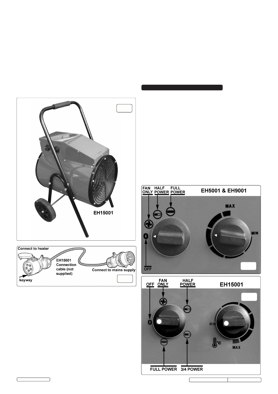
5.3. Referring to either fig.6 or fig.7, set the thermostat dial to the
maximum setting (fully clockwise).
5.4. The heater will switch on when the power setting selector is set
to one of the power settings.
NOTE:
It will take up to three minutes for the heater to reach
optimum temperature.
5.5. Once the room reaches the required temperature, turn the
thermostat dial slowly counter-clockwise until the thermostat
clicks, leave the dial in this position and the room temperature
will be maintained at this setting. The heater will continue to
operate until the power switch is turned to the OFF position.
5.6. For fan only operation, turn the power/fan selector to the fan
only setting and set the thermostat to its minimum setting.
5.7. When not in use, disconnect the heater from the mains supply.
Store it in a safe, dry, childproof location.
fig.6
fig.4
Original Language Version
4.4. CONNECTING EH15001 TO MAINS SUPPLY
4.4.1. The EH15001 heater is supplied with a protected 5 pin
connector mounted on the side of the control housing. In order
to connect to the mains it will be necessary to have the
extension cable shown in fig.5 made up by a qualified
electrician. (This connector is not supplied with the machine.)
The cable should be no shorter than 1.8mtr and no longer than
3.0mtr.
4.4.2. Before connecting the EH15001 to the mains ensure that the
selector switch is set to OFF and the thermostat is set at
minimum.
4.4.3. Hold open the protective cover on the socket connector on the
extension lead as shown above and present it to the heater
connector in the correct orientation so that the spigot on the
heater connector passes into the keyway on the socket
connector. Push the socket connector fully home.
4.4.4. Connect the other end of the extension cable to the mains
supply.
4.5. EH15001 THERMOSTATIC PROTECTION.
4.5.1. The EH15001 has a thermal cut out to prevent the unit
from overheating for any reason, especially if the air input is
restricted. If the temperature of the front grille reaches 45ºC a
a thermal cutout will operate, turning off the heating elements.
When the fan has cooled the unit to 40ºC, normal thermostatic
operation will resume.
4.5.2.
AUTO COOLING. It is recommended that the thermostat should
be set to the minimum to cool the unit prior to switching off. If
the unit is switched off when operating at full temperature, and
the front grille has reached 45ºC, the time delay thermostat will
keep the fan running to cool down the unit. When the front grille
has cooled to 40ºC the fan will stop running.
4.5.3.
NOTE: Auto cooling will only function if the unit is plugged
into the mains and the mains is ON.
fig.5
fig.7
EH15001, EH9001, EH5001 Issue: 9(L) - 05/05/14
© Jack Sealey Limited