Fig.1 fig.2 fig.3, Introduction 3. specification 4. assembly – Sealey EH30001 User Manual
Page 2
2. INTRODUCTION
3. SPECIFICATION
4. ASSEMBLY
Electric fan heater for industrial applications. Features three
heat settings and adjustable thermostat control with fan only
option. Auto cooling system to prevent unit from overheating
during use. A totally dry heat with no condensation, no gas,
no fumes and no smell. Ideal for workshops, garages etc.
Supplied with three phase chassis mounted plug (extension lead
required).
Model No: . . . . . . . . . . . . . . . . . . . . . EH30001
IP Class: . . . . . . . . . . . . . . . . . . . . . . . . . IPX4
Max. Power:. . . . . . . . . . . . . . . . . . . . .30000W
Supply: . . . . . . . . . . . . . . . . . . . . . . .415V-63A
Heat Settings: . . . . . . . . . . . . . 15000/30000W
Dimensions (WxDxH (mm)): 645 x 565 x 860
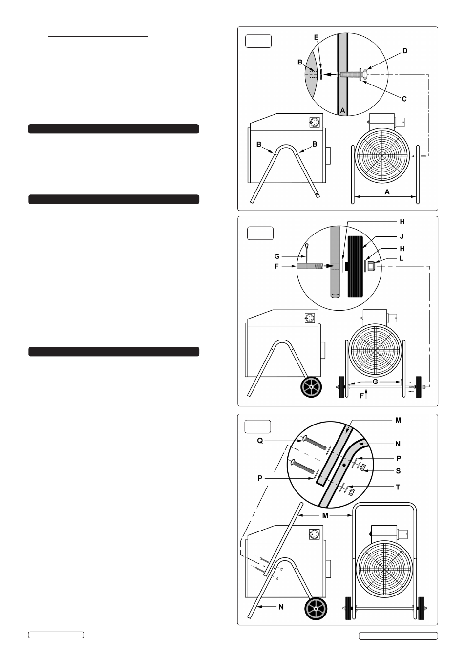
fig.1
fig.2
fig.3
4.3. ASSEMBLY OF THE HANDLE. (Ref. fig.3)
4.3.1. Slide a plain washer over each of the four M5 x 50mm bolts
supplied.
4.3.2. Lay the 'U' shaped handle frame onto the front face of the leg
frames and align the two holes at each end of the handle frame
with the two holes in each leg frame. Insert two bolts at each
joint as indicated in fig.3.
4.3.3. Whilst continuing to support the handle frame slide a plain
washer (P) followed by a split washer (T) onto the end of each
protruding bolt and retain them with a nut (S). Tighten all four
nuts with an 8mm spanner.
4.1. ASSEMBLY OF THE LEGS. (Ref. fig.1)
4.1.1. On either side of the heater body there are two threaded inserts
(B) for mounting the 'V' shaped leg frames (A). Note that the
axle hole at the shorter end of the 'V' frames should be
orientated towards the back of the heater.
4.1.2. Take two M8 x 40mm bolts (D) and slide a plain washer (C) onto
each one. Insert a bolt through each of the mounting holes on
the leg frame and slide a split washer (E) over each protruding
bolt. Align the bolts with the two threaded inserts (B) on the
heater body and screw them down securely.
4.1.3. Mount the other 'V' frame to the other side of the heater body in
the same way.
4.2. ASSEMBLY OF THE WHEELS. (Ref. fig.2)
4.2.1. Take the axle rod (F) and insert it through the holes in the 'V'
frames so that the threaded rod ends protrude equally either
side. Retain the axle rod in this position by inserting split pins
(G) through the holes situated just on the inside of each leg
frame.
4.2.2. Slide a plain washer (H) over each end of the axle rod, followed
by a wheel (J) followed by anther plain washer (H).
4.2.3. Screw a nyloc nut (L) onto each end of the axle by hand until it
begins to bite. Hold one nut steady with a 19mm spanner and
progressively tighten each nut until it bottoms out on the thread.
Original Language Version
1.2.4.
COMMON SENSE PRECAUTIONS
DO NOT operate the heater when you are tired or under the
influence of alcohol, drugs or intoxicating medication.
DO NOT stand on the heater.
DO NOT use the heater with wet hands or when there is water
on the power cord.
Ensure that the heater is correctly turned off when not in use
and store in a safe, dry, childproof location.
DO NOT use the heater for anything other than its intended
purpose. It is designed to provide heat in enclosed areas larger
than 4m³, such as workshops and other industrial areas. It is
not suitable for drying clothes or laundry.
IMPORTANT!
This unit is designed to raise the ambient temperature of an
entire room, the temperature of the air coming out of the front
of the heater will be warmer than the general temperature of the
room, but there may not be a significant increase owing to the
large volume of air passing over the element. For the same
reason, the element is hot during operation, but does not
glow. The room temperature depends on room size, insulation
and the ambient temperature, which will increase as the room
gets warmer.
EH30001 Issue: 4(L) - 05/05/14
© Jack Sealey Limited