Fig.5, Fig.6 fig.7 5. maintenance, Fig.8 air filter housing screw – Sealey SA2415 User Manual
Page 3: Fig.9
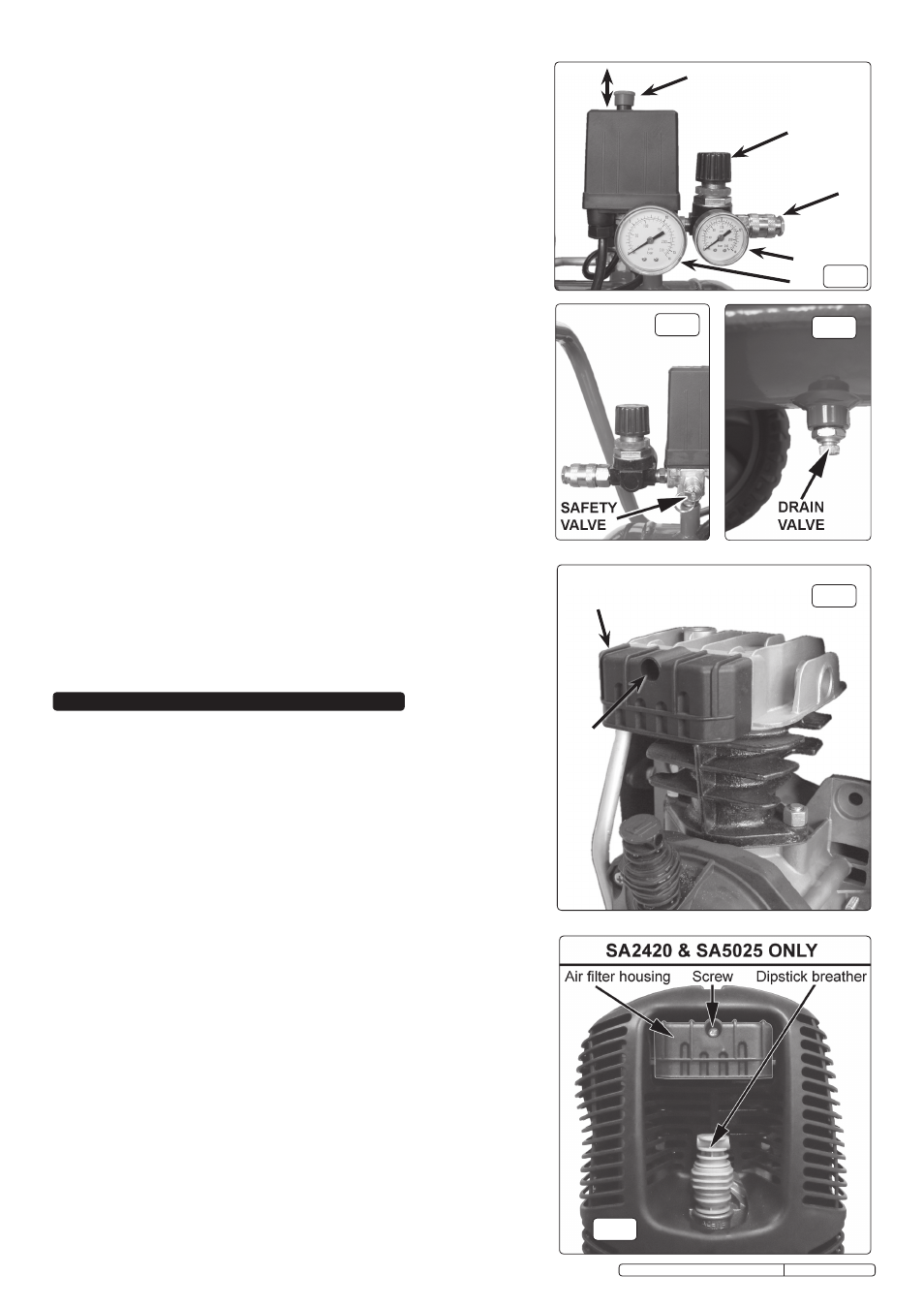
fig.5
ON
1
2
3
4
5
OFF
fig.6
fig.7
5. MAINTENANCE
In order to keep the compressor in good working condition, periodic
maintenance is essential.
IMPORTANT! Failure to carry out maintenance tasks may invalidate the
warranty on your compressor.
WARNING! Before performing any maintenance operation, switch off the
compressor, disconnect from electricity supply and release all air from the
tank.
5.1. Operations to be carried out after the first 50 working hours:
a)
Check that all bolts/nuts are tight, particularly those retaining the
crankcase and cylinder head.
b)
Replace the lubricating oil - see para 5.4.
5.2.
Operations to be carried out weekly:
a)
Drain condensation by opening the valve located under the tank (fig.7).
Place a container under the valve and open the valve by turning
anticlockwise.
b)
Check oil level and, if necessary, top up.
WARNING! Take care if there is still pressure inside the cylinder as water could
flow out with coinsiderable force.
Recommended pressure 1 - 2bar max.
5.3. Operations to be carried out every 50 hours
(or more frequently, if the compressor operates in a very dusty atmosphere):
a)
Unscrew the air filter housing and remove the filter element (fig.8 or 9
depending on model) and wash in soapy water, rinse and dry. Do not
operate the compressor without the filter as foreign bodies or dust could
seriously damage the pump.
b)
Check for oil leaks.
5.4. Operations to be carried out every 100 hours:
a)
Replace the lubricating oil. For oil specifications see 5.7.
Remove the dipstick/breather plug (see fig.4.A) then unscrew oil drain
plug ‘B’, draining the oil into a container.
Drain when the compressor is hot so that oil drains rapidly and
completely. Incline compressor to ensure complete drainage.
Replace oil drain plug and refill through the dipstick/breather aperture.
Do not overfill. Replace dipstick.
b)
Check the automatic cut-out at max. pressure and the automatic cut-in at
2bar below.
fig.8
Air filter
Housing
Screw
4.1.
STARTING THE COMPRESSOR
PULL ON/PUSH OFF. The switch is a push/pull type as shown in fig.5.1. To
turn the compressor ‘ON’ pull the switch knob upwards. To turn the compressor
‘OFF’ push the knob downwards.
4.2.
Check that the ON/OFF switch is in the “OFF” position, the regulator tap (fig.5.2)
is closed, the output gauge (fig.5.4) must read Zero ‘0’ bar.
4.3.
Plug mains lead into mains supply and start the compressor by moving the
main switch to the ‘ON’ position.
4.4.
When starting the compressor for the first time, leave it running with no air tools
connected to the air outlet (fig.5.3). Make sure that pressure in the tank rises
and that the compressor stops automatically when the maximum pressure value
allowed - written on the plate and shown on the gauge (fig.5.5) - is achieved.
The compressor will now operate automatically. The pressure switch stops the
motor when the maximum tank pressure is reached and restarts it when the
pressure falls below the minimum threshold - approx. 2 bar (29psi) less than the
maximum pressure.
4.5.
Stop the compressor by moving the main switch to the ‘OFF ‘position. The
compressed air inside the compressor head will flow out, making the restart
easier and preventing the motor from being damaged.
DO NOT, other than in
an emergency
, stop the compressor by switching off the mains socket, or by
pulling the plug out, as the pressure relief will not then operate and motor
damage may result upon restart.
When the compressor runs correctly and is stopped correctly there will be:
(a) a whistle of compressed air when the motor stops,
(b) a protracted whistle (about 20-25 seconds) when the compressor starts
with no pressure in the tank.
4.6.
The output pressure is regulated by the pressure regulator (fig.5.2). Lift and
turn the knob clockwise to increase pressure and anticlockwise to reduce it -
push knob down to lock in required position. To determine the correct working
pressure for any piece of equipment check the corresponding manual. When
the compressor is not being used set the regulated pressure to zero so as
to avoid damaging the pressure regulator.
NOTE: a) If the motor does not cut in and out, but runs continuously when using an air
appliance, the capacity of the compressor may be too small for the
equipment or tool.
b) The gauge (fig.5.5) indicates the pressure inside the main tank, NOT the
pressure supplied to the air equipment. Should the pressure in the main tank
exceed the pre-set switch maximum, a safety valve will activate.
WARNING! For this reason Do noT tamper with, or adjust, the switch or
safety valve.
3
When the compressor is not in use, it should be switched off,
disconnected from the mains supply and the air drained from the tank.
Original Language Version
fig.9
SA2415, SA2420, SA5020, SA5025 Issue: 5 - 21/05/12