Isolate before opening control cabinet, Fig.4, Fig.7 5. maintenance – Sealey SAC65010B User Manual
Page 3: Fig.5, Fig.6
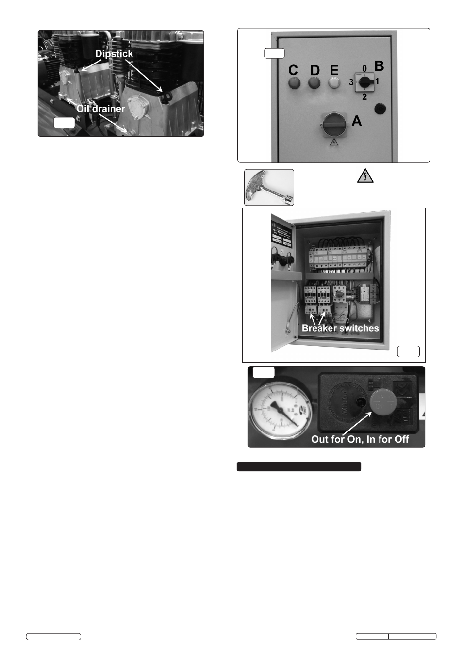
fig.4
4.2. Operation
WARNING! Ensure that you have read, understood and
apply Section 1 Safety Instructions.
IMPORTANT! The use of extension leads not
recommended as the resulting voltage drop reduces
motor, and therefore pump performance, and could
cause damage to the compressor.
NOTE: Take care when selecting tools for use with the
compressor. Air tool manufacturers normally express the
volume of air required to operate a tool in cubic feet per
minute (cfm). This refers to free air delivered by the
compressor (‘air out’) which varies according to the pressure
setting.
DO NOT confuse this with the compressor
displacement which is the air taken in by the compressor
(‘air in’). ‘Air out’ is always less than ‘air in’ due to losses
within the compressor.
In order to keep the compressor in good working condition,
periodic maintenance is essential.
IMPORTANT! Failure to carry out maintenance tasks may
invalidate the warranty on your compressor.
WARNING! Before performing any maintenance operation,
switch off the compressor, disconnect from the electricity
supply and release all air from the tank (except for 5.3.a)
5.1. Operations to be carried out after the first 50 working hours:
a) Check that all bolts/nuts are tight, particularly those retaining
the crankcase and cylinder head.
b) Replace the lubricating oil - see para 5.5.a. shown in fig.4.
5.2. Operations to be carried out weekly:
a) Drain condensation by opening the valve located under the
tank (fig.7). Place a container under the valve and open the
valve by turning anti-clockwise.
WARNING! Take care if there is still pressure inside the cylinder
as water could flow out with coinsiderable force.
Recommended pressure 1 - 2bar max.
b) Check oil level and, if necessary, top up.
fig.7
5. MAINTENANCE
Original Language Version
© Jack Sealey Limited
SAC65010B Issue: 1 - 24/12/14
fig.5
ISOLATE BEFORE OPENING
CONTROL CABINET
STARTING THE COMPRESSOR Refer to fig.5
4.2.1. Connect the mains supply and pull the pressure switch up to its
'on' position, see fig.7.
4.2.2. Turn the master power switch 'A' on the control unit to the 'I'
position - power On (signified by the white indicator light
'E' coming on.)
4.2.3.
Turn switch 'B' to start the compressor, position 1 is
compressor unit 1 operating only, position 2 is compressor unit
2 operating only, position 3 is both compressor units operating
at the same time, at staggered starting times (timer in fig.6).
4.2.4. When starting the compressor for the first time, leave it running
with no air tools connected to the air outlet. Make sure that the
pressure in the tank rises and that the compressor stops
automatically when the maximum pressure value allowed;
written on the plate and shown on the gauge
(fig.7) is
achieved. The compressor will now operate automatically.
The pressure switch stops the motor when the maximum tank
pressure is reached and restarts it when the pressure falls
below the minimum.
4.2.5. To stop the compressor, first turn the main switch "A" (fig.5) to
the '0' position and then turn the switch "B" (fig.5) to the '0'
position. The compressed air inside the compressor heads will
exhaust via check valves (fig.10), making the restart easier and
preventing the motors from being damaged.
DO NOT, other
than in an emergency
, stop the compressor by switching off at
the mains, or by pulling the plug out, as the pressure relief will
not then operate and motor damage may result upon restart.
4.2.6. The motors of the compressor are supplied with a manual reset
thermal-overload, located on the terminal board cover, see fig.6.
When the breaker is tripped, use the key to open the door, wait
for a few minutes, and reset the overloads manually.
4.2.7. The safety device is automatic. When the thermal overload is
tripped, wait for a few minutes to cool. The pressure switch is
released to the 'O' Off position.
NOTE:
a) If the motor does not cut in and out, but runs continuously
when using an air appliance, the capacity of the compressor
may be too small for the equipment or tool.
b) The gauge (fig.7) indicates the pressure inside the main
tank,
not the pressure supplied to the air equipment.
Should the pressure in the main tank exceed the pre-set switch
maximum, the safety valve will activate.
WARNING! For this reason DO NOT tamper with, or adjust,
the switch or safety valve.
fig.6
On/Off switch sited on the tank (fig.2)