Fig.1 fig.2 fig.3 fig.1a, Ab c, Assembly – Sealey AK4562D User Manual
Page 2
4.1.
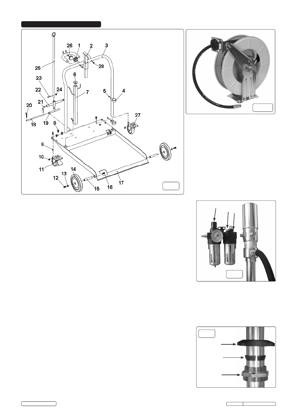
Trolley Assembly (fig.1)
4.1.1. Attach the two castor wheels (11 & 27) to the base plate (17) using bolts (8) washers (9)
and nuts (10).
4.1.2. Turn the base plate upside down and attach the axles (15) to the base plate using hex
bolts (16) and then slide the wheels (14) onto the axles and secure using washers (13)
and hex bolts (12). Turn the base plate over so that it is now supported on its wheels.
4.1.3. Slide the two pump support brackets (4) onto the handle (3) and attach them using hex
grub screws (5).
4.1.4. Slide the accessory support (7) onto the other side of the handle and attach using hex
grub screw (5), insert stopper (6) into the top of the accessory support.
4.1.5. Slide the handle assembly into the base plate until it bottoms out on the stops and secure
with two hex grub screws (5).
4.1.6.
Slide the drum holder support (2) into the handle and secure using knob (1).
4.1.7. Thread knob (1) into the handle support (26) and then attach handle support to the main
handle (3) using bolts (28).
4.1.8. Slide the handle grip (22) onto the movable handle (25), insert handle joint (19) into the
base of the moveable handle and secure using bolt (23) and nut (24). Align the handle
assembly to the brackets on the base plate and slide handle pin (18) through and lock
into position with R-clips (20).
4.1.9. Adjust the pump support brackets, so that they fully support the pump assembly and
check all fixings are tight.
4.1.10. Place the AK4567D retractable hose reel (fig.1A) onto the back of the base plate and
secure using four bolts, washers and nuts (not shown in fig.1).
A
B C
4.2.
Pump and Air Regulator/Lubricator Assembly
4.2.1. Apply a small amount of liquid thread sealant onto the threads of the air inlet of the pump
and attach the air regulator/lubricator (fig.2).
WARNING! DO NOT allow thread sealant to enter the pump.
4.2.2. Attach the outlet pipe to the male outlet thread on the pump and attach the male threaded
end of the pipe to the retractable hose reel.
4.2.3. Attach the outlet of the retractable hose reel to the Digital Hose End Meter.
4.2.4. Attach the nozzle valve pipe assembly to the outlet of the Digital Hose End Meter.
WARNING! DO NOT overtighten the swivel connections.
4.2.5. Slide the locking nut, locking ring and the barrel nut onto the pick up probe of the pump
(fig.3), screw the locking nut onto the barrel nut to lock the assembly to the pick up probe.
4.2.6. Insert the pump assembly into the support brackets on the trolley and hang the meter
onto the accessory support bracket.
Locking
Nut
Lock Ring
Barrel Nut
AK4562D Issue: 2(P) - 02/09/14
Original Language Version
© Jack Sealey Limited
4. ASSEMBLY
fig.1
fig.2
fig.3
fig.1A