Fig.4 fig.5 fig.6 – Sealey CST806 User Manual
Page 3
and M8 lock nuts (30).
4.4.
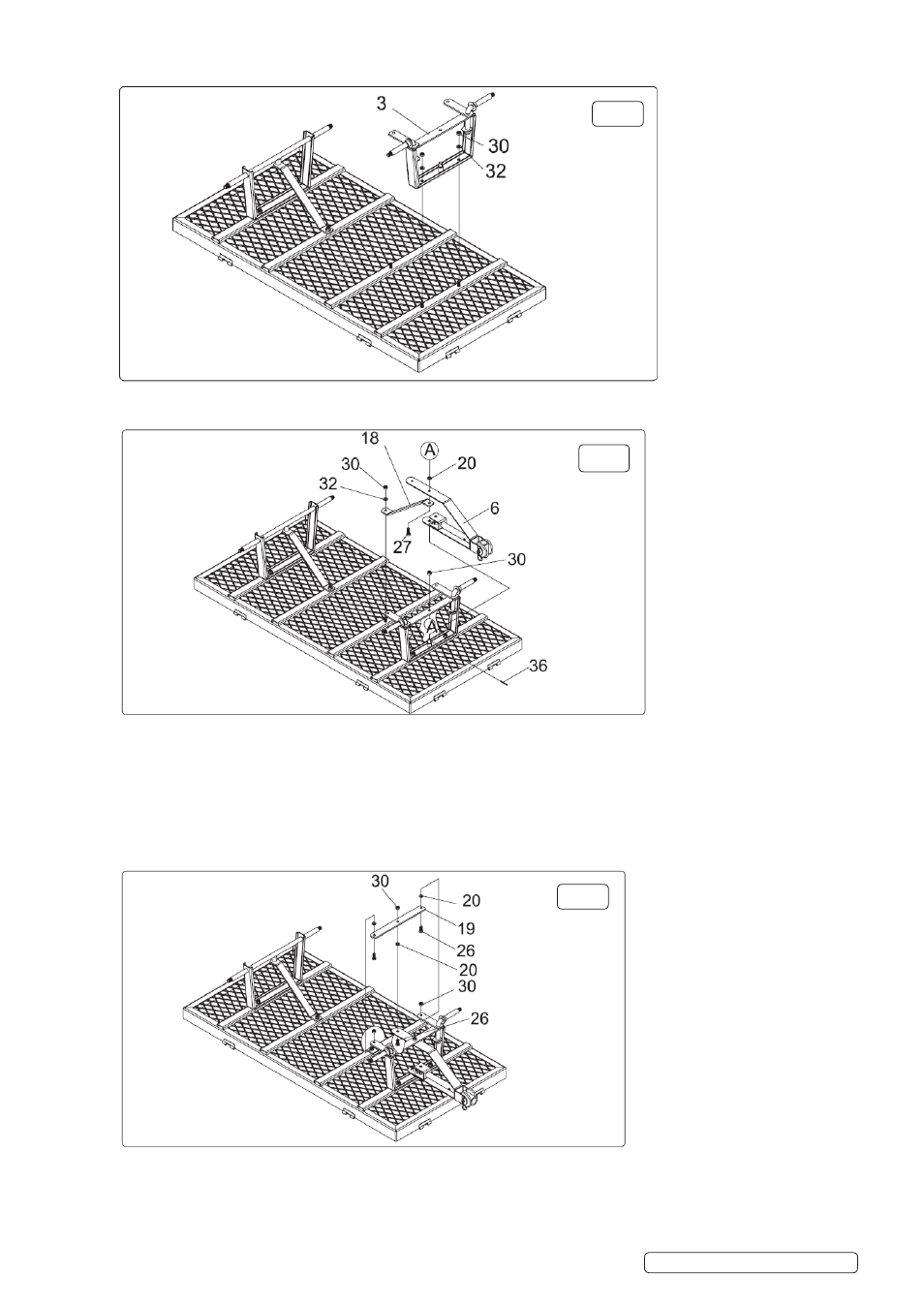
FRONT WHEEL BRACKET ASSEMBLY See fig.4
4.4.1.
Attach the front wheel bracket assembly (3) to the bottom panel (1), using 8mm flat washers (32) and M8 lock nuts (30).
4.5.
FRONT SUPPORT BAR AND TURNING BRACKET See fig.5 and parts list on back page
4.5.1.
Connect turning bracket (6) onto front wheel bracket (3).
4.5.2.
Place turning bracket (6) over boss (see A fig.5 and C on parts list on back page).
4.5.3.
Secure with pin (36).
4.5.4.
Connect bottom of turning bracket (6) to front wheel bracket (3) (see A on fig.5 and D and E on parts list on back page), using
M8x25 bolt (27) and nylon washer (20) and M8 lock nut (30).
4.5.5.
Fit wheel support bar (18) to bottom panel (1), using M8 flat washer (32) and M8 lock nut (30) and turning bracket (6) (see A on
fig.5).
4.6.
FLAT PLATE ASSEMBLY See fig.6 and F, G and H on parts list on back page
4.6.1.
Place the flat plate (19) between the front wheel bracket (3) and the turning bracket (6) using M8x20 bolts (26), nylon washer (20)
and M8 lock nuts (30).
fig.4
fig.5
fig.6
CST806 | Issue 2(I) 15/05/15
Original Language Version
© Jack Sealey Limited