Sealey CST997 User Manual
Platform truck, Cst997.v2, Fig.1
InstructIons for:
platform truck
MoDEL no's:
cSt997.V2
thank you for purchasing a sealey product. Manufactured to a high standard this product will, if used according to these instructions
and properly maintained, give you years of trouble free performance.
1. SafEtY INStructIoNS
IMPORTANT: plEaSE rEaD tHESE INStructIoNS carEfullY. NotE tHE SafE opEratIoNal rEQuIrEmENtS, WarNINGS & cautIoNS.
uSE tHE proDuct corrEctlY aND WItH carE for tHE purpoSE for WHIcH It IS INtENDED. faIlurE to Do So maY cauSE
DamaGE aND/or pErSoNal INJurY aND WIll INValIDatE tHE WarraNtY. plEaSE kEEp INStructIoNS SafE for futurE uSE.
2. SpEcIfIcatIoN
3. INtroDuctIoN
4.1
check contents against the parts list, if anything is missing
or damaged contact your local sealey dealer.
4.2.
turn the truck bed upside down and lay it on a level floor
with something underneath it to prevent it being scratched.
4.3.
Bolt the rear axle support (see fig.1-3) to the bed using two
8 x 20mm bolts, two washers and two 8mm nuts
(see fig.1-20).
4.4.
slide one end of each rear axle brace (see fig.1-4&5) over
the axle and bolt each one to the bed as indicated in fig.1
using two 8 x 20mm bolts, two washers and two 8mm nuts
for each brace. tighten all nuts securely.
4. aSSEmBlY
model No. . . . . . . . . . . . . . . . . . . . . . . . . . . . . . . . . . . . cSt997.V2
Max. Load. . . . . . . . . . . . . . . . . . . . . . . . . . . . . . . . . . . . . . . . .200kg
tyre Diameter. . . . . . . . . . . . . . . . . . . . . . . . . . . . . . . . . . . . .250mm
tyre thickness . . . . . . . . . . . . . . . . . . . . . . . . . . . . . . . . . . . . .90mm
Depth of cart . . . . . . . . . . . . . . . . . . . . . . . . . . . . . . . . . . . . .220mm
cart Width . . . . . . . . . . . . . . . . . . . . . . . . . . . . . . . . . . . . . . .480mm
cart Length. . . . . . . . . . . . . . . . . . . . . . . . . . . . . . . . . . . . . . .930mm
overall Height. . . . . . . . . . . . . . . . . . . . . . . . . . . . . . . . . . . . .570mm
Always distribute the load evenly over the surface of the bed.
Do not overload the truck - see specification.
Do not leave unattended, especially when loaded, unless the
wheels are chocked or the truck is otherwise secured.
Do not use truck on uneven ground and do not run over curbs or
steps - use a ramp.
Do not allow others to ride on the truck.
Do not use the truck if any part is damaged, paying particular
attention to the wheels.
Do not inflate the tyres more than 30p.s.i.
Heavy-duty steel with hinged mesh construction. cushioned grip pull
handle with smooth steering action for easy manoeuvrability. steel
centred pneumatic wheels allow transport over the toughest terrain.
Drop-down sides, for easy loading, are also removable, allowing use
as a flatbed for oversized items. suitable for a variety of warehouse,
office, garden and domestic hauling applications.
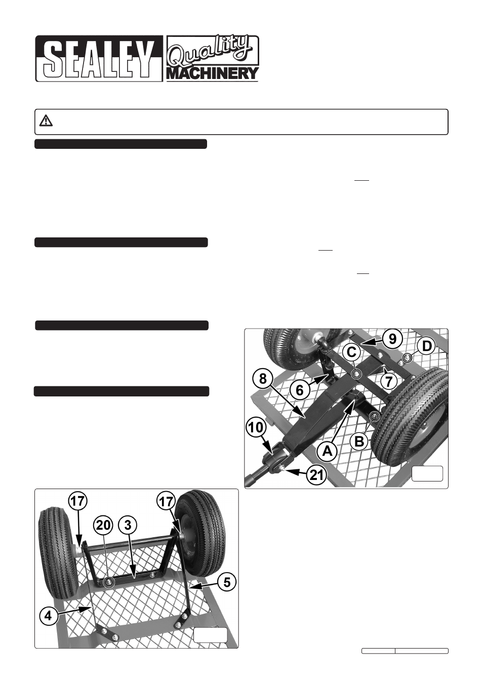
fig.1
4.5
Assemble the front support/steering assembly completely
before bolting it to the bed.
4.6
Attach the steering link connector to the axle guides
(see fig.2-9) using two 8 x 15 short shoulder bolts with
matching nuts and washers. notE: Attach the steering
link connector on the bed side of the axle guides.
4.7
Place the yoke (see fig.2-8) into position in the steering
assembly ensuring that the short arm of the yoke drops onto
the pivot pin in the centre of the front axle support
(see fig.2-A). secure in position using a cotter pin through the
hole in the end of the pivot pin.
4.8
Bolt the long arm of the yoke to the steering link connector
using one 8 x 15 short shoulder bolt with matching 6mm nut
and washer.
4.9
Attach the centre front axle brace (see fig.2-7) to the steering
assembly at point ‘c’. use the long shoulder bolt together
with matching 6mm nut and washer.
4.10 now bolt the whole steering assembly to the bed. use two
8 x 20mm bolts to fix the front axle support at points ‘B’ x 2
and two 8 x 20mm bolts to fix the centre brace at point ‘D’.
fig.2
4.11
slide wheel spacer bushings onto both the front and rear
axles. Place a wheel onto each axle with the valve stem
facing outwards. Place a plain washer onto each axle
followed by spring washer and secure each wheel with a
locking nut.
4.12 turn the cart upright onto its wheels and attach the pull
handle using the plastic coupling. secure with the 8 x 60mm
pull handle bolt, washer and nut.
4.13 Attach each hinged side-piece to the bed using the quick
release pins provided (see fig.4-A). Attach the side with the
cut out portion to the handle end of the bed. (see fig.3)
cst997.V2 Issue: 1 - 18/01/09