Fig. 3 fig.4, Fig. 2 – Sealey PT1150SC User Manual
Page 2
5.1.
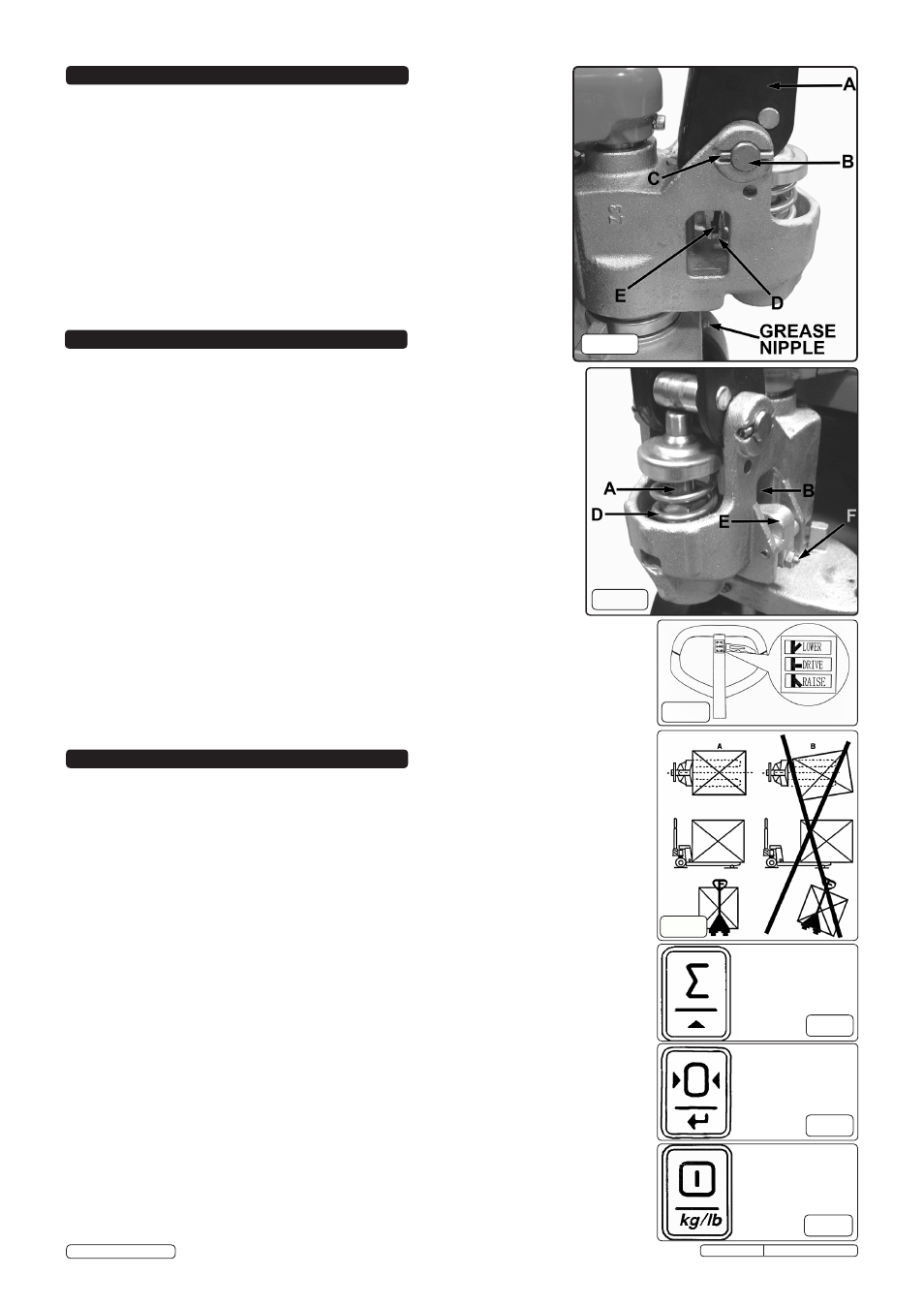
The operating handle control lever can be set to one of three positions, as shown in fig.4.
They
are:
5.1.1.
RAISE:
Control lever in the DOWN position.
5.1.2.
DRIVE:
Control level in the CENTRAL position.
5.1.3.
LOWER: Control lever in the UP position.
5.2.
If the above positions have been altered, they can be restored by carrying out the
following adjustments.
5.2.1. If the forks rise whilst pumping in the
DRIVE position, turn the adjusting nut (fig.2D)
on the adjusting bolt (fig.2E) or the screw (fig.3F) clockwise, until the pumping
action does not raise the forks and the
DRIVE position functions normally.
5.2.2. If the forks lower whilst pumping in the
DRIVE position, turn the adjusting nut (fig.2D)
or the screw (fig.3F) counterclockwise, until the pumping action does not lower the
forks.
5.2.3. If the forks do not lower when the control lever is in the
LOWER position, turn the
adjusting nut (fig.2D) or the screw (fig.3F) clockwise, until raising the control lever
lowers the forks.
NOTE: Check the DRIVE position again by repeating paragraphs 5.2.1 and 5.2.2 to ensure
that the adjusting nut (fig.2D) and the screw (fig.3F) are still in the correct position.
5.2.4. If the forks do not rise when pumping in the
RAISE position, turn the adjusting nut
(fig.2D) or the screw (fig.3F) counterclockwise until the forks rise.
NOTE: Check the LOWER and DRIVE positions again from paragraphs 5.2.1 to 5.2.3 to
ensure that the
LOWER and DRIVE positions are functioning correctly.
5. OPERATING HANDLE ADJUSTMENT
fig. 3
fig.4
6. OPERATION
6.1.
Operating the Pallet Truck
WARNING! An operator must be fully conversant with the safety instructions in Section 1.
6.1.1. Prior to operating the pallet truck, check the wheels, the operating handle and the fork unit to
ensure they are fit for purpose.
6.1.2. Move the truck with the operating handle control lever in the
DRIVE position, as this makes the
operating handle easier to move and also depressurises the hydraulic pump.
DO NOT overload
the pallet truck.
6.1.3. Ensure that the goods being transported are placed on the middle of the pallet truck forks. Refer
to fig.5. Depress the power ON switch on the right-hand side of the console.
6.2.
Measuring Gross Weight
6.2.1. Set the operating handle control lever to the
LOWER position and lower the pallet truck.
6.2.2. Place the pallet forks under the load to be weighed. Ensure that the load is correctly balanced.
Refer to fig.5.
6.2.3. Set the operating handle control lever to the
RAISE position and pump the operating handle.
Ensure that the pallet is clear of the floor.
NOTE: The reading indicated on the console is the gross weight, i.e the weight of the goods and the
pallet.
6.3.
Measuring Net Weight
NOTE: This method is used for goods packed on a standard pallet.
6.3.1. With an empty pallet on the forks, pump the operating handle with the control level in the RAISE
position until the pallet is clear of the ground, press the “TARE” key refer to fig.7. The console
will then display
0kg.
6.3.2. If you were to remove the pallet from the pallet truck forks. The console will then display minus
the weight of the pallet, (e.g. -20kg)
6.3.3. Add items to the pallet to see the weight then depress the "TARE" key (fig.7). Add another item
observe the weight and repeat until the pallet is full, press and hold the totalling key (fig.6) for 3
seconds to reveal the amount of items weighed and their combined weight excluding the pallet.
NOTE: To switch measurement between kilograms and pounds, depress the “FUNCTION” key (fig.8).
fig.5
fig.6
fig.7
fig.8
TOTALLING
KEY
TARE KEY
FUNCTION
KEY
4.1.
Connect the operating handle to the hydraulic pump body using the pivot pin
(fig.2B) with a hole in the centre. Insert from left to right.
4.2.
Align the pivot hole on the base of the handle with the pivot holes on the main
casting.
4.3.
Insert the pivot shaft (using a soft hammer) insuring that the holes in either end of
the shaft (fig.2B) are aligned with the grooves on the outer sides of the main
casting (fig.2C).
4.4.
When the shaft is properly aligned drive a roll pin through either end of the shaft.
4.5.
Using thin nosed pliers, pass the end of the chain and with adjusting nut through
the hole in the centre of the pivot shaft.
4.6.
Put the handle (fig.4) into its lowest position (
RAISE).
4.7.
Lift the actuating lever (fig.3E) against its spring pressure and slide the adjusting
bolt underneath so the chain (fig.2E) rests in between the forks.
fig. 2
4. OPERATING HANDLE ATTACHMENT
Original Language Version
PT1150SC.V2 Issue:3(SP)-26/04/13
© Jack Sealey Limited