Operating instructions, Installation – Sealey MT400 User Manual
Page 2
4.1
RAISING THE PLATFORM
check that the hinged part of the platform is in the raised, horizontal position and is
properly locked in place with the sliding support bars fully inserted into the main platform.
refer to fig.7. (mt700.V3 onlY).
4.1.1 Before use, check that the lift is level on a suitable surface, and that the platform is fully
lowered.
4.1.2 take the overrun guard and insert it into the recesses in the platform. (see fig.1)
4.1.3 Place the loading ramp onto the two locating bolts on the lower main frame of the
platform (see fig.1)
WARNING! ensure that there will be adequate clearance between the underside of the
vehicle and the point where the loading ramp and platform meet. failure to do so
may cause damage.
4.1.4 Position the vehicle on the platform, apply the handbrake, and we recommend securing
with straps through the strap hooks on the ramp
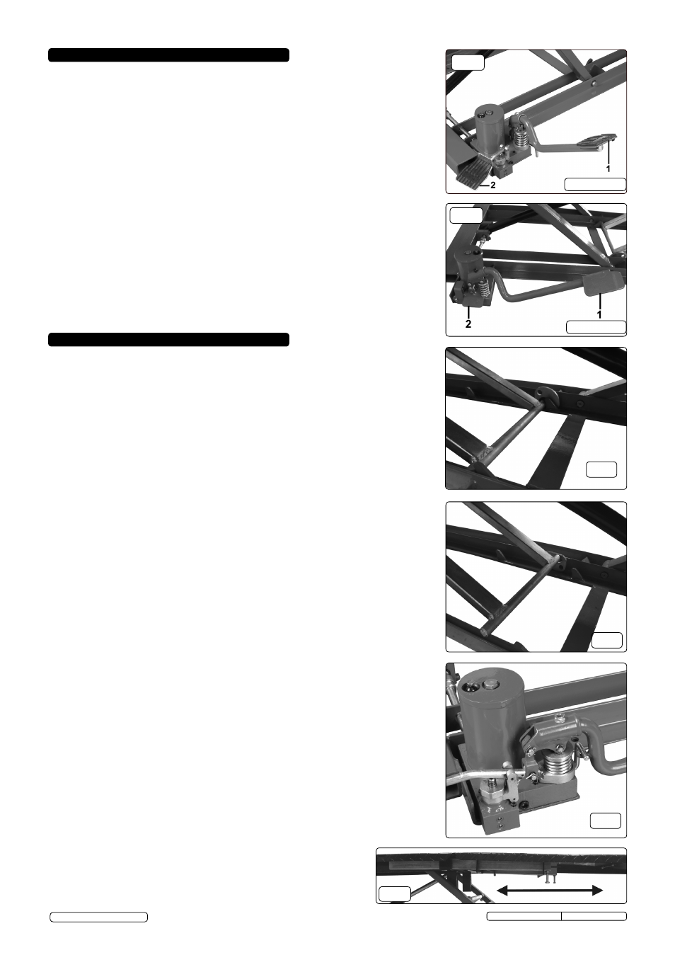
4.1.5 raise the platform by pumping the foot pedal (fig.2.1, fig.3.1). continue to pump until
the locking frame and cam have passed over the first locking point as shown in fig.5.
Briefly depress the descent valve (see fig.2.2, fig.3.2) so that the locking frame rests
firmly against the stop points. If greater working height is required, continue to operate
the pump lever until the locking frame has passed the second locking point. ensure that
the locking frame is firmly against the locking points. the platform must always be raised
to one of the two locking points. never stop/leave the platform before the first stop point
or in between locking points.
4.1.6 If the handbrake needs to be released for servicing purposes ensure that wheels are
chocked and the vehicle is definitely restrained with straps before the handbrake is
released.
4.1.7 the hinged portion of the platform may be lowered if desired for greater access. to do
this the platform must be supported by a person at either side whilst the sliding support
bars are moved out from underneath the main platform. When the bars are fully retracted
the flap can be lowered. (mt700.V3 onlY).
4.1.8 the removable loading ramp may be lifted out of the way if desired.
4.2
LOWERING THE PLATFORM
4.2.1 When work is complete, check under the platform to ensure that there are no obstructions
and that it is safe to lower the unit. ensure that there are no electrical cables, air lines or
hoses of any sort passing beneath the platform.
4.2.2 Place the loading/unloading ramp into position if previously removed.
4.2.3 to disconnect the safety mechanism raise the platform by about 3cm and lift the locking
frame sufficiently to allow the cam to rotate so that its flat side is upwards. see fig.5. this
raises the height of the locking frame and allows it to pass over the stop point as the
platform is lowered.
4.2.4 slowly operate the descent valve on the pump (see fig.2.2, fig.3.2) in order to lower the
platform.
4.2.5 as the platform continues to lower, the safety cam will automatically rotate back to the
safety position. as the locking frame approaches the next stop point it will be necessary
to stop the descent and rotate the cam again by lifting the locking frame.
4.2.6 When the platform has fully descended, release/unchock the vehicle and
back it off the platform using the brakes to control its progress.
4.2.7 When finished with the platform move the descent valve anti-clockwise
and the foot pedal down and clockwise to store them underneath the
platform and out of the way. (see fig.6)
4. OPERATING INSTRUCTIONS
3.1
INSTALLATION SITE:
the lift should be transported to its installation site by fork lift truck.
3.1.1 In general there should be a minimum clearance of 1 metre all around the lift in order to
give operators adequate access to the lift and the vehicle on it. a clear approach to the
ramp is also required to safely load a vehicle.
3.1.2 the working area should have a solid, flat and even floor. the area should be well lit
and free from extraneous materials.
3.1.3 the lift can be free standing or fixed to a solid concrete floor using m10 x 100mm
expansion bolts.
3.2
EXPELLING AIR FROM THE SYSTEM:
3.2.1 to bleed the system, first operate the foot pump pedal (see fig.2.1 / fig.3.1) continuously
through its full stroke until the platform reaches its full height and the locking frame and
cam have passed over the second stop position.
3.2.2 raise the platform slightly and lift the locking frame so that the cam rotates downwards
(see fig.4) allowing the lower bar of the locking leg to pass over the stop point when
the platform is lowered using the descent valve lever on the foot pump. (fig.2.2 / fig.3.2).
3.2.3 repeat this process several times until smooth ascent and descent are achieved.
3.3
CHECKS BEFORE USE: make the following checks before using the lift for the first
time.
3.3.1 check that there is no sign of breakage or damage to the mechanical structure of the lift.
3.3.2 check that all mechanical safety devices are functioning.
3.3.3 ensure that there are no oil leaks.
3.3.4 check that all circlips attached to the pivots are in place.
3. INSTALLATION
Original Language Version
mt400.V3, mt700.V3 Issue: 1 - 11/06/13
Fig.4
Fig.5
Fig.2
Fig.6
MT700.V3
Fig.3
MT400.V3
Fig.7
© Jack sealey limited