Fig.1 fig.2 – Sealey GSC110385SP User Manual
Page 2
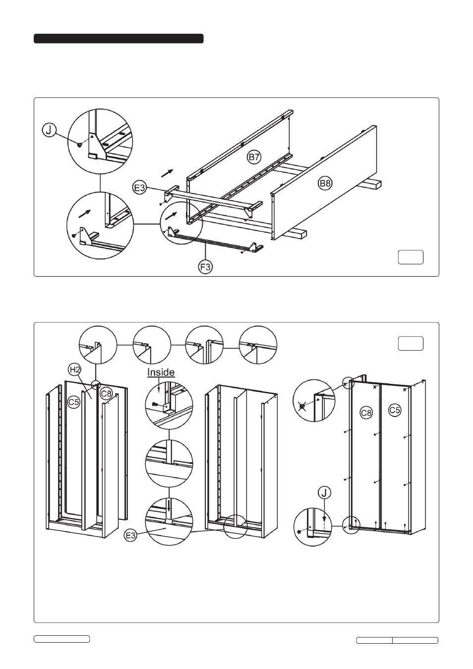
4.1. Assemble the cabinet, using the following diagrams and referencing the parts list/diagram overleaf.
4.2. Insert and slide E3 front base bracket and f3 back base bracket into the bottom of B7 left side panel and B8 right side
panel. Attach with 1 screw J into each of the four corners. Use a trestle table or a workbench for convenience (fig.1).
4. ASSEMBLY
4.3. Acquire the help of a second person for this stage. Stand unit upright and insert H2 middle panel into the hole in E3
front base bracket. Fix it in place using 1 J self tapping screw from the rear. Install C5 left back panel, and then C8 right
back panel over the top of panel C5. Use self tapping screws J to attach panels (fig.2) (
NOTE - don't fix screws to the
top corners at this stage).
Fig.1
Fig.2
Original Language Version
GSC110385SP Issue: 1 - 16/07/12
© Jack Sealey Limited