Sealey APIBP2100 User Manual
Page 2
3.1
see fig.5. Back panel kits are available for all three sizes of
bench and are an optional extra to be purchased separately.
aPibP1500 .............. Back panel assembly for API1500
aPibP1800 .............. Back panel assembly for API1800
aPibP2100 .............. Back panel assembly for API2100
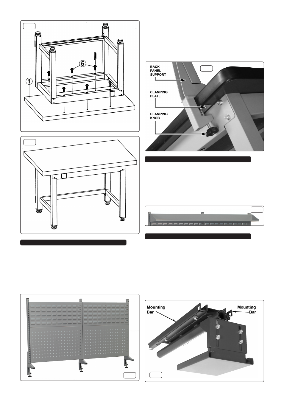
take the three back panel supports and clamp them to the
back edge of the bench ensuring that a clamping plate is
inserted between the clamping knob spindle and the underside
of the bench top as shown in fig.6. Adjust the positions of the
uprights until the tool panels can be slotted into position
followed by the bin panels above them as shown in fig.5 . on
the outer uprights the back panels should occupy the inner line
of slots leaving one row of slots visible.
4.1 three widths of shelf unit can be purchased as an optional
extra to match the three back panel kits. the shelves hook
into the outer uprights as shown in fig.7 and stand away from
the panels slightly allowing them to be put at any height.
aPi11........................ shelf for APIBP1500
aPi12 ....................... shelf for APIBP1800
aPi13 ....................... shelf for APIBP2100
5.1 A Vice Mounting clamp
aPi10 can be can be purchased as an
optional extra to provide a base plate to which a vice can be
mounted. the mounting clamp also allows the vice to be
stored out of the way, below the bench, when a full free work
surface is required.
5.2 fig.8 below shows the clamp in the stowed away orientation.
the mounting bars have to be removed from the clamp and
positioned under the bench as shown in fig.9-V. Place each
bar in a diagonal orientation under the bench top then turn it
so that the ends are over the upper beams. Allow the slots in
the ends of the mounting bars to rest over the upturned edges
of the beams.
3. back Panel asseMblY
4. shelF asseMblY
5. Vice MountinG claMP asseMblY
fig.3
fig.4
fig.6
fig.7
fig.8
fig.5