Fig.7 fig.8 fig.9 – Sealey AP02DFC User Manual
Page 3
01284 757500
01284 703534
Sole UK Distributor
Sealey Group,
Bury St. Edmunds, Suffolk.
www.sealey.co.uk
Web
NOTE: It is our policy to continually improve products and as such we reserve the right to alter data, specifications and component parts without prior notice.
IMPORTANT: No liability is accepted for incorrect use of this product.
WARRANTY: Guarantee is 12 months from purchase date, proof of which will be required for any claim.
INFORMATION: For a copy of our catalogue and latest promotions call us on 01284 757525 and leave your full name, address and postcode.
AP02DFC
Issue No: 1 - 06/08/08
3.6
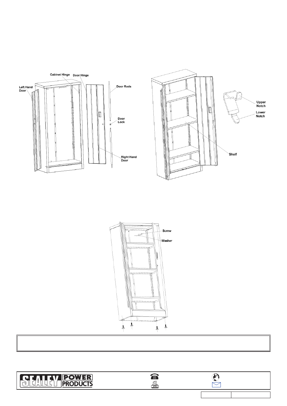
DOOR ASSEMBLY (Fig.7)
3.6.1 Upright the cabinet and place on a level floor. Check the cabinet for squareness, if required slacken off appropriate bolts to adjust the
cabinet and then re-tighten.
3.6.2 Select the right hand door which is the door with the lock assembly and align the hinge with the companion hinge on the right hand side
panel, slide the two hinge components together. Repeat for the left hand door.
3.7
SHELF ASSEMBLY (Fig.8)
3.7.1 Fit shelf clips to the front of the side panels, there are round holes located near the hinges on the side panels, locate a clip at the
desired height and a corresponding clip on the opposite side. The clips are fitted by inserting the upper notch of the clip into the hole and
then push and snap the lower notch in the hole below.
3.7.2 Select one of the shelves, the back of the shelf is denoted by having square cutouts and the front of the shelf has round cutouts, insert the
shelf into the cabinet at an angle so that the back of the shelf slots into the square cut-out at the rear of the unit, then lower the front of the
shelf onto the front clips. Repeat for all the other shelves.
Fig.7
Fig.8
Fig.9
3.8
FINAL ASSEMBLY (Fig.9)
3.8.1 Carefully lay the unit onto its back, using the packing material to protect the unit.
3.8.2 Attach the four leg levellers to the bottom of the unit.
3.8.3 Upright the unit, position the unit where it is to be located and adjust the legs to level the unit and to ensure that the doors will open and
close freely.
3.8.4 Use the supplied screw and washer to attach the cabinet to the wall, if it is a masonry wall alternative fasteners will be required.
DO NOT overtighten the screw too much or distortion of the back of the unit will occur.
3.8.5 Use a mild solution of detergent and water and wipe the unit down with a soft cloth.
Parts support is available for this product.
To obtain a parts list and diagram please log on to www.sealey.co.uk, email [email protected] or phone 01284 757500