Fig.6, Fig.5, Maintenance – Sealey PP35PLUS User Manual
Page 5: Troubleshooting 8. rating plate, Problem possible cause remedy
DANGER! Ensure that the machine is disconnected from the power supply before performing service or maintenance on any part of
the unit, cables or torch.
6.1.
The inverter
DO NOT open the unit. Service and maintenance of the machine must only be undertaken by an authorised service agent.
6.1.1.
Keep the machine clean by wiping with a soft cloth. Do not use abrasives.
6.1.2.
Periodically check to ensure that the carrying handle is in good order and condition. If not replace it
immediately.
6.1.3.
Ensure that the front and rear air vents are not blocked.
6.2.
Cables and leads
6.2.1.
Check to ensure cables and leads are in good condition. If damaged, contact your authorised service
agent.
6.2.2.
Keep cables and leads clean. Do not use solvents.
6.3.
Torch
Check torch regularly. Maintenance will depend on frequency and type of usage and is essential for correct
and safe use of the torch.
WARNING! Ensure that the torch is cool before attempting any maintenance. Always re-assemble the torch
in the correct order as shown in fig.5. Never use tools to tighten nozzle components, hand tighten only.
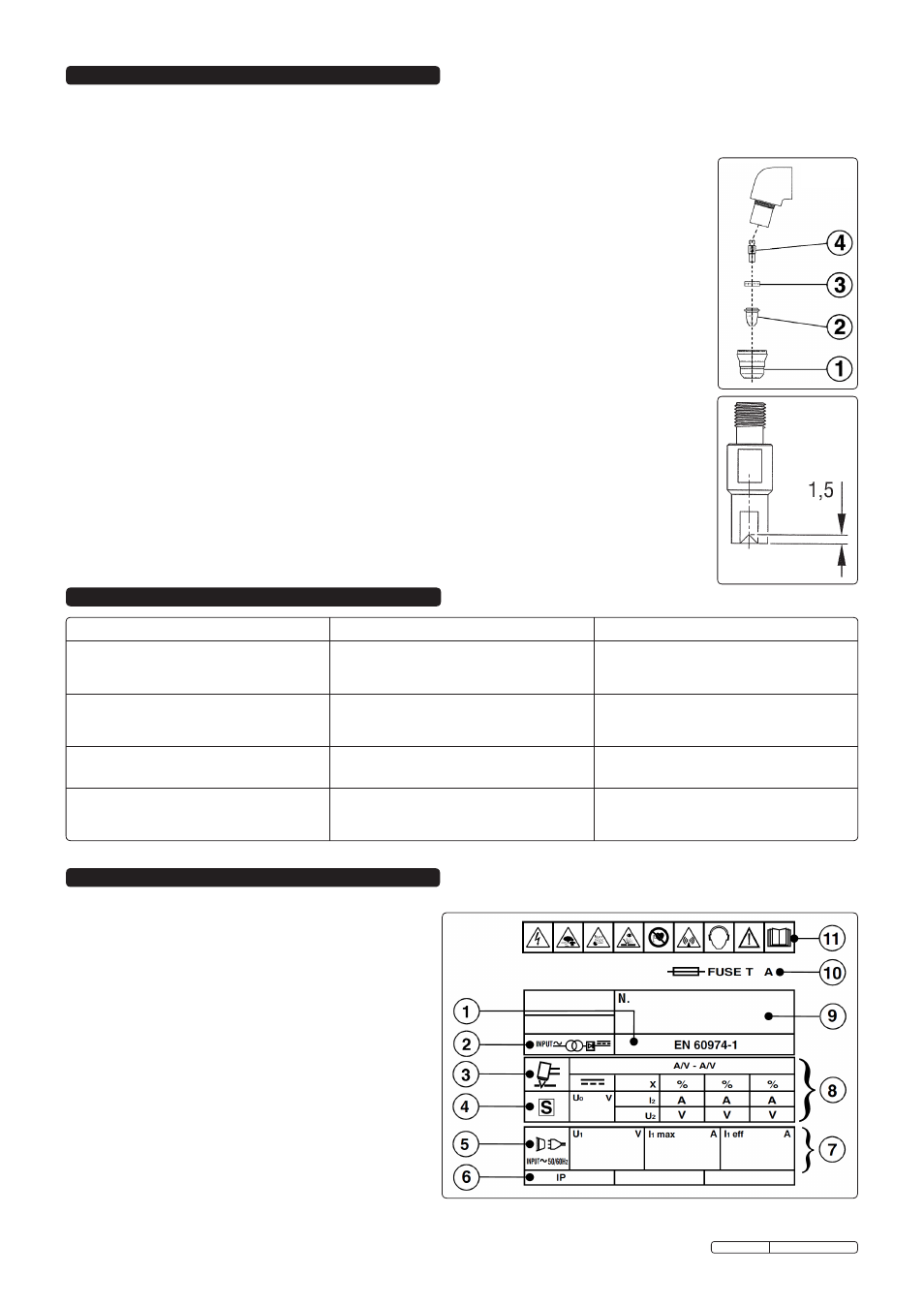
Manually dismantle the torch nozzle head (fig.5).
6.3.1.
Cap (fig.5.1).
Clean cap and check to ensure it is not damaged (including distortion, burns, cracks).
If in any doubt, replace.
6.3.2.
Electrode (fig.5.2).
Check the build-up on the emitting surface of the electrode. When the build-up is approximately 2mm
replace the electrode.
NOTE: We recommend that the electrode and nozzle are changed at the same time.
6.3.3.
Air distribution ring (fig.5.3).
Check that the ring is not burned or cracked and that the airflow holes are not obstructed. If damaged,
replace.
6.3.4.
Nozzle (fig.6.4).
If surface is oxidised, clean with extra fine abrasive paper. Check wear of the plasma arc hole and the
inner and outer surfaces. If hole has widened, or nozzle is damaged in any way, replace it. The nozzle “V”
crater should be 1.5mm in depth (fig.6).
6. MAINTENANCE
fig.6
7. TROUBLESHOOTING
8. RATING PLATE
On the rear of the inverter is the rating plate, giving the following
data:
1 - The standard relating to the safety and construction of
welding and cutting equipment.
2 - Symbol referring to the internal structure of the machine.
3 - Symbol referring to the plasma cutting procedure.
4 - S: Indicates that cutting may be carried out in environments
with a heightened risk of electric shock e.g. very close to
large metallic objects.
5 - Power Supply: AC, number of phases and frequency.
6 - Rating of internal protection provided by casing.
7 - U
1
: Rated supply voltage.
- I
1max
: Maximum RMS current absorbed.
- I
1eff
: Effective current supplied.
8 - U
0
: Maximum open-circuit voltage.
- l
2
, U
2
: Current and corresponding voltage.
- X: Duty cycle, based on a 10 minute period. 30% indicates
3 minutes cutting and 7 minutes rest, 100% indicates
continuous cutting.
- A/V-A/V: Cutting current range and corresponding voltages.
9 - Serial number. Specifically identifies each machine.
10 - Rating of delayed action fuse for supply protection
11 - Symbols referring to safety.
fig.5
PROBLEM
POSSIBLE CAUSE
REMEDY
Insufficient penetration or excessive scoria settlement.
Too fast a cutting speed.
Torch is too tilted.
Workpiece is too thick.
Electrode and nozzle are worn out.
Slow the cutting speed.
Adjust the torch tilt.
Confirm workpiece thickness and re-check technical data.
Replace electrode and nozzle.
Interruption of cutting arc.
Cutting speed too low.
Excessive distance between torch and workpiece.
Electrode is worn out.
Intervention of the protection system.
Increase the cutting speed.
Decrease the distance between torch and workpiece.
Replace electrode and nozzle.
Check warning lights and take appropriate action.
The torch is cutting at tilt when you wish it to be
perpendicular.
Torch position not correct.
Asymmetric wear of nozzle hole and/or wrong assembly of
torch parts.
Re-align the torch.
Check assembly (see fig.5) and change nozzle if necessary.
Excessive wear of nozzle and electrode.
Air pressure too low.
Contaminated air (humidity-oil).
Excessive pilot arc ignitions in the air.
Nozzle holder damaged.
Increase air pressure (see Section 5).
Check air supply system (see Sections 4, 5 & 7).
Do not casually turn the torch on and off.
Change the nozzle holder.
Original Language Version
PP35PLUS Issue: 2 - 15/05/12