Compatability – Sealey 140XT User Manual
Page 3
8. COMPATABILITY
WARNING! Ensure the welder is disconnected from the electrical mains power supply before attempting any service or
maintenance tasks outlined below.
7.1.
Keep the welder clean and dry at all times. Use a dry cloth to clean the unit.
7.2.
Keep all electrodes clean and dry and ensure all cables are in good condition.
7.3.
Inspect the welder regularly, with a frequency depending on use and the dustiness of the environment. Remove dust deposits from the
transformer using a jet of dry compressed air, (Max 10bar).
7.4.
At the same time make sure that the electrical connections are tight and check the wiring for damage to the insulation.
7.5.
If necessary use a very thin layer of high temperature grease, to lubricate the moving parts of the regulators (threaded shaft, sliding
surfaces, shunts etc).
7.6.
After these light maintenance operations ensure that the welder covers are replaced and that all fastening screws are fully tightened.
7.7.
Use an authorised service agent for any other maintenance or service requirements.
WARNING! Never perform welding operations with the covers removed.
Electrode Diameter (mm) Welding Current (Amp)
Min
Max
1.6 . . . . . . . . . . . . . . . . . .25 . . . . . . . . .50
2.0 . . . . . . . . . . . . . . . . . .45 . . . . . . . . .60
2.5 . . . . . . . . . . . . . . . . . .55 . . . . . . . .100
3.2 . . . . . . . . . . . . . . . . . .80 . . . . . . . .140
4.0 . . . . . . . . . . . . . . . . . .85 . . . . . . . .160
WARNING! If you have no welding experience, we recommend you seek supervised training from an expert source.
6.1. Introduction. Your welder features a single phase transformer with a drooping characteristic suitable for welding with an alternating
current using stick electrodes with diameters from 1.5mm to the highest electrode diameter as shown on the chart in Fig.6.
6.2.
Current regulation. The intensity of the welding current can be adjusted by means of a manually operated magnetic shunt. See Fig.1-3.
To increase the current turn the knob clockwise whilst making reference to the graduated scale on the top of the machine (See Fig.3).
To decrease the current turn the knob anti clockwise. Note: Set the current to the desired level before commencing welding.
DO NOT operate the current regulation mechanism whilst welding is in progress.
6.3. Thermostatic Protection.
6.3.1.
Temperature Control Indicator Light.
When the machine is overheating, it cuts off the power and the indicator light comes on. When the temperature has dropped to the
recovery temperature, the machine can automatically restart and the indicator light will go off.
See Fig.1-5.
6.3.2
Temperature Protection Indicator Light.
If the Temperature Controller fails, the protector will cut off the power and the indicator light comes on. Temperature protection can not
resume automatically. If needed, please follow the methods below for recovery operations:
1. Turn off the machine's power.
2. Open the cover of the machine.
3. When the temperature protector pops up on the red contacts, such as in the picture right, it means the machine has cut off.
4. Press the red contacts on the thermal protection this means the machine is now in a normal state. As you use larger
welding rods you may experience a temporary current shut off. The larger the welding rod, the greater the current required,
consequently, the hotter the machine will become and the quicker it will cut out.
6.4.
Setting up the welder.
6.4.1. Ensure the machine is turned off from the mains power supply. (See fig.1-2).
6.4.2. Attach the earth clamp to a point on the workpiece that has been cleanly ground to provide good contact. Attach it as close as
possible to the area you will be welding.
6.4.3. Select the diameter of electrode to be used in relation to the type of weld to be made. Consideration should be given to the fact that
higher current values should be used for flat welding, whereas for vertical or over head welding lower current values are required.
Insert the electrode into the electrode holder. Ensure there is a good connection. Ensure welding surfaces are kept clean and free
from grease, or oil.
6.4.4. Establish the welding current required in relation to the diameter of electrode you are using by making reference to the table in Fig.6.
6.4.5. Set the current required in amps using the control knob on the front panel. See Fig.1-3. The current set can be read from the
graduated scale on the top of the machine. See Fig.3.
6.5.
Commencing Welding It is advisable to practice on scrap metal first, especially where potentially difficult welds are to be undertaken.
WARNING! Remember to wear a full face welding mask, gauntlets and protective clothing and ensure you have read,
understood and apply safety instructions. Wear goggles whilst chipping slag.
6.5.1.
DO NOT switch on the power supply until you are fully ready to start welding.
6.5.2. Place the face mask in front of your face.
6.5.3. To strike the arc tap the electrode lightly on the workpiece as if striking a match.
DO NOT hit the electrode on workpiece as this may
damage the stick.
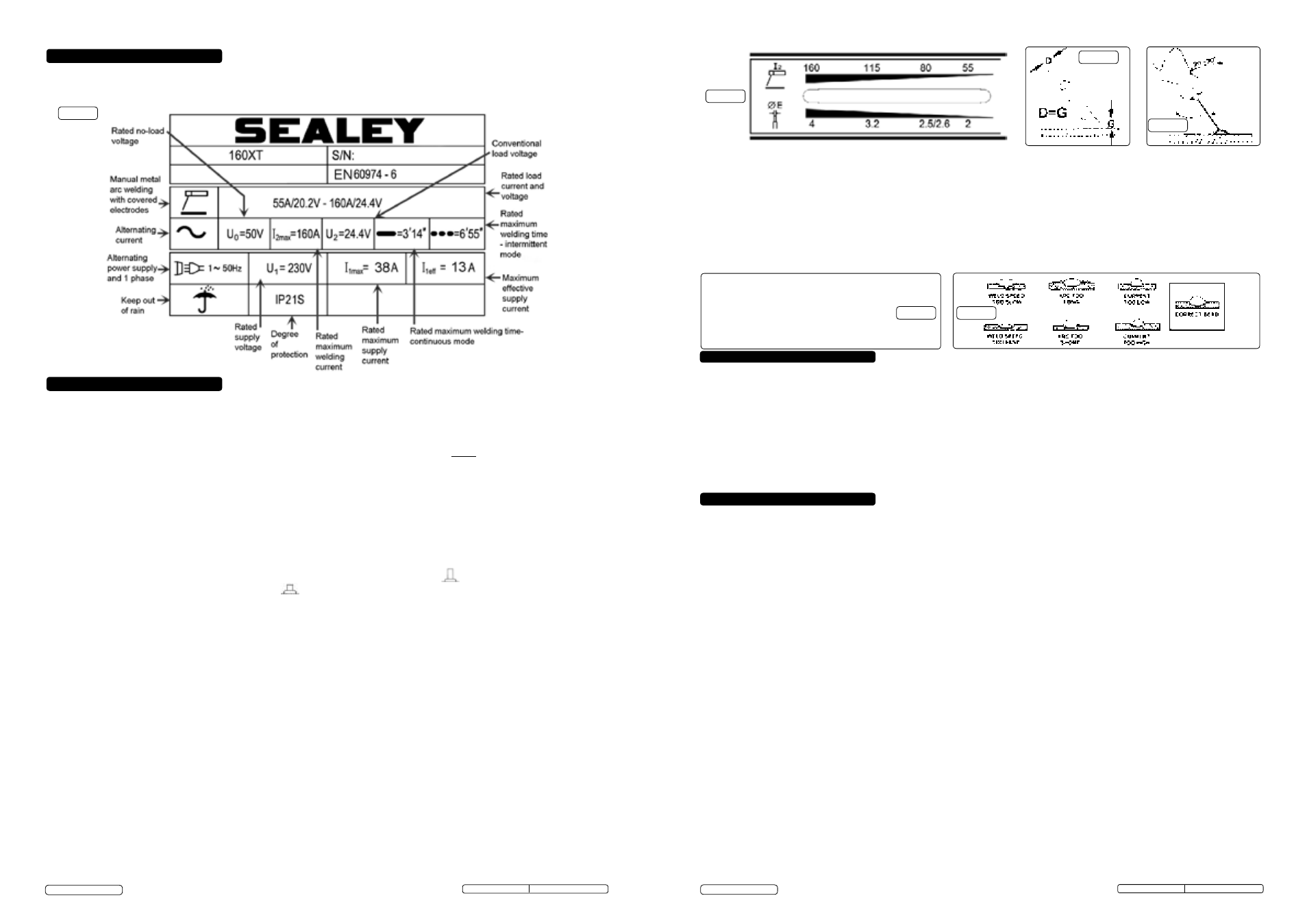
FOR FURTHER CLARIFICATION OF SYMBOLS REFER TO BRITISH STANDARD EN 60974-6
(For actual ratings of your model refer to the top cover)
Fig.2
Fig.3
Fig.4
Fig.5
Fig.6
Fig.7
5. RATINGS PLATE GUIDE
6. OPERATION
7. MAINTENANCE
6.5.4. As soon as the arc is struck maintain a steady gap between the end of the electrode and the workpiece equal to the diameter of the
electrode in use (See Fig.4). Try to maintain this gap continuously through out the duration of the weld. The electrode should also be held
at an angle of 20° to 30° from the vertical. (See Fig.5).
6.5.5. At the end of the weld bead, move the tip of the electrode backwards in order to fill the weld crater. Quickly lift the electrode from the
weld pool to extinguish the arc. Refer to Fig.7 for a welding fault analysis.
6.5.6. If the electrode sticks, you may be holding it too close to the workpiece. Pull sharply to the left, and then to the right to free the
electrode.
6.5.7. After welding, chip off the slag with a chipping hammer. Wear goggles.
6.5.8. Switch off the welder and disconnect it from the mains power supply. Remember that the workpiece and the electrode will still be very
hot.
WARNING! Use pliers to remove the hot consumed electrodes or to move the hot welded pieces.
6.5.9. When welding has finished remove the electrode from the electrode holder as a safety precaution.
8.1.
THIS EQUIPMENT IS IN CONFORMITY WITH THE EUROPEAN STANDARD ON THE ELECTROMAGNETIC
COMPATIBILITY OF ARC WELDING EQUIPMENT AND SIMILAR PROCESSES (E.G. ARC AND PLASMA CUTTING)
8.2.
Protection against interference (EMC). The emission limits in this standard may not, however, provide full protection against
interference to radio and television reception when the equipment is used closer than 30m to the receiving antenna. In special cases,
when highly susceptible apparatus is being used in close proximity, additional mitigation measures may have to be employed in order
to reduce the electromagnetic emissions. At the same time there could occur some potential difficulties in having electromagnetic
compatibility in a non-industrial environment (e.g. in residential areas). Therefore it is most important that the equipment is used and
installed according to the following instructions.
8.3.
Installation and use. The user is responsible for installing and using the equipment according to these instructions. If electromagnetic
disturbances are detected, then it shall be the responsibility of the user of the equipment to resolve the situation with the
technical assistance of the supplier. In some cases this remedial action may be as simple as earthing the circuit (see Note). In
other cases it could involve constructing an electromagnetic screen, enclosing the welding power source and the work, complete with
associated input filters. In all cases the electromagnetic disturbances shall be reduced to the point where they are no longer
troublesome.
Note: The welding/cutting circuit may or may not be earthed for safety reasons. Changing the earthing arrangements should only be
authorised by a person who is competent to assess whether the changes will increase the risk of injury, e.g. by allowing parallel
welding/cutting circuit return paths which may damage the earth circuits of other equipment. Further guidance is given in IEC 974-13
’Arc Welding Equipment - Installation and Use.’
8.4.
Assessment of area. Before installing the equipment the user shall make an assessment of potential electromechanical problems in
the surrounding area. The size of the surrounding area to be considered will depend on the structure of the building and other
activities that are taking place. The surrounding area may extend beyond the boundaries of the premises.
The following shall be taken into account :
a) Other supply cables, control cables, signalling and telephone cables, above, below and adjacent to the welding equipment.
b) Radio and television transmitters and receivers.
c) Computer and other control equipment.
d) Safety critical equipment, e.g. security monitoring of industrial equipment.
e) The health of people in the vicinity, e.g. persons fitted with a pacemaker or hearing aid.
f) Equipment used for calibration or measurement.
g) The immunity of other equipment in the environment. The user shall ensure that other equipment being used in the environment is
compatible. This may require additional protective measures.
h) The time of day that welding and other activities are to be carried out.
8.5.
Mains supply. The equipment should be connected to the mains supply according to these instructions. If interference occurs, it may
be necessary to take additional precautions such as filtering of the mains supply. Consideration should also be given to shielding the
supply cable of permanently installed equipment in metallic conduit or equivalent. This shielding should be connected to the power
source so that good electrical contact is maintained between the conduit and the welding power source enclosure.
140XT.V2, 160XT.V2 Issue: 2 (SP) - 30/04/15
Original Language Version
© Jack Sealey Limited
140XT.V2, 160XT.V2 Issue: 2 (SP) - 30/04/15
Original Language Version
© Jack Sealey Limited