Maintenance, Operating instructions 5. environmental conditions – Sealey 200XTD User Manual
Page 6
7. MAINTENANCE
WARNING! Ensure the welder is disconnected from the electrical mains power supply before attempting any service or
maintenance tasks outlined below.
7.1
Keep the welder clean and dry at all times. Use a dry cloth to clean the unit.
7.2
Keep all electrodes clean and ensure all cables are in good condition.
7.3
Inspect the welder regularly, with a frequency depending on use and the dustiness of the environment. Remove dust deposits from the
transformer using a jet of dry compressed air, (Max 10bar).
7.4
At the same time make sure that the electrical connections are tight and check the wiring for damage to the insulation.
7.5
If necessary use a very thin layer of high temperature grease, to lubricate the moving parts of the regulators (threaded shaft, sliding
surfaces, shunts etc.).
7.6
After these light maintenance operations ensure that the welder covers are replaced and that all fastening screws are fully tightened .
7.7
Use an authorised service agent for any other maintenance or service requirements.
WARNING! Never perform welding operations with the covers removed.
6. OPERATING INSTRUCTIONS
5. ENVIRONMENTAL CONDITIONS
Electrode Diameter (mm) ......Welding Current (Amp)
1.6 ................................25min ...............50max
2.0 ................................40min ...............80max
2.5 ................................60min ...............110max
3.2 ................................80min ...............160max
4.0 ................................105min .............185max
5.0 ................................130min .............220max
WARNING! If you have no welding experience, we recommend you seek supervised training from an expert source.
6.1 Introduction. Your welder features a single phase transformer with a drooping characteristic suitable for welding with an alternating
current using stick electrodes with diameters from 1.5mm to the highest electrode diameter as shown on the chart below (See fig.9).
6.2 Current regulation. The intensity of the welding current can be adjusted continuously by means of a manually operated magnetic
shunt. See fig.5-6 & fig6-5. The value of the current (I²) may be read in amps on the graduated scale on the top panel of the
welder (See fig.4).
6.3 Thermostatic Protection. When the machine becomes overheated the built in automatic protection cuts off the supply and a yellow
lamp illuminates on the front panel. See fig.5-3 & fig.6-2. When the machine has cooled the light goes out and the supply is
automatically restored. As you use larger welding rods you may experience a temporary current shut off. The larger the welding rod, the
greater the current required, consequently, the hotter the machine will become and the quicker it will cut out.
6.4 Setting up the welder.
6.4.1 Ensure the machine is turned off from the mains power supply. See fig.5-1 & fig.6-1.
6.4.2 Insert the quick connector for the work clamp lead into the socket marked with the work clamp symbol. See fig.5-5 & fig.6-4. Rotate the
connector fully through 180º to ensure a secure connection. Attach the work clamp to a point on the workpiece that has been cleanly
ground to provide good contact. Attach it as close as possible to the joint to be made.
6.4.3. Insert the quick connector for the electrode holder lead into the socket marked with the electrode holder symbol. Rotate the connector
fully through 180º to ensure a secure connection. See fig.5-4 & fig.6-3.
6.4.4 Select the diameter of electrode to be used in relation to the type of joint to be made. Consideration should be given to the
fact that higher current values should be used for flat welding, whereas for vertical or over head welding lower current values are
required. Insert the electrode into the electrode holder. Ensure there is a good connection. Ensure welding surfaces are kept clean and
free from grease, or oil.
6.4.5 Establish the welding current required in relation to the diameter of electrode you are using by making reference to the table below (fig.9.)
6.4.6 Set the current required in amps using the control wheel on the front panel. See fig.5-6 & fig.6-5. Turn the control clockwise to increase the
current, and anti-clockwise to decrease the current. The current set can be read from the graduated scale on the top panel of the machine.
See Fig.4..
6.5 Commencing welding. It is advisable to practice on scrap metal first especially where potentially difficult welds
are to be undertaken.
WARNING! Remember to wear a full face welding mask, gauntlets and protective clothing, and
ensure you have read, understood and apply safety instructions. Wear goggles whilst chipping slag.
6.5.1 DO NOT switch on the power supply until you are fully ready to start welding.
6.5.2 WARNING! (220XTD & 250XTD) DO NOT switch from one voltage to another whilst welding.
6.5.3 Place the face mask in front of your face.
6.5.4 To strike the arc, tap the electrode lightly on the workpiece as if striking a match.
DO NOT hit the electrode on
the workpiece as this may damage the stick.
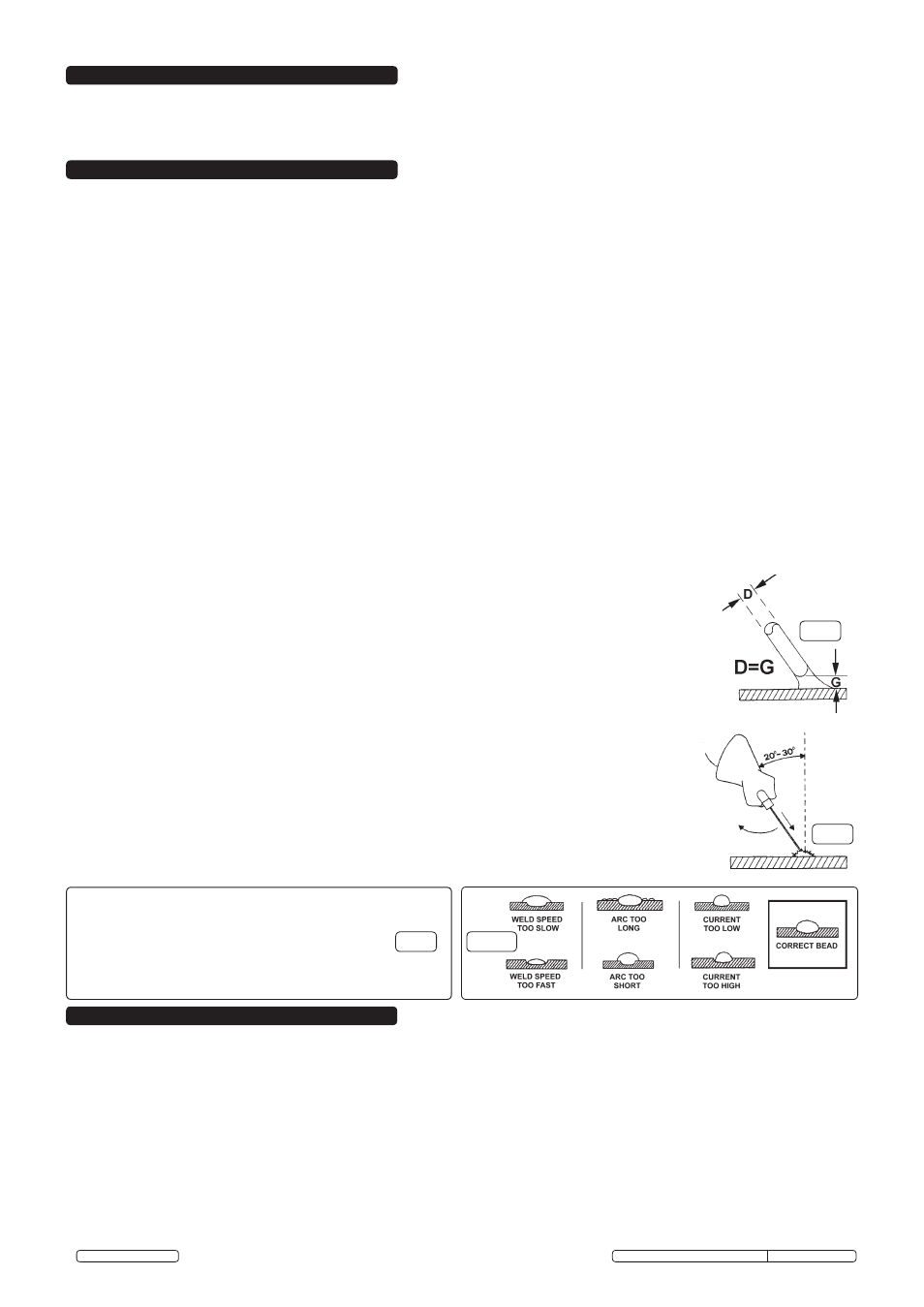
6.5.5 As soon as the arc is struck maintain a steady gap between the end of the electrode and the workpiece
equal to the diameter of the electrode in use (See fig.7). Try to maintain this gap continuously through out
the duration of the weld. The electrode should also be held at an angle of 20° to 30° from the vertical. (See
fig.8).
6.5.6 At the end of the weld bead, move the tip of the electrode backwards in order to fill the weld crater. Quickly
lift the electrode from the weld pool to extinguish the arc. Refer to fig.10 for a welding fault analysis.
6.5.7 If the electrode sticks, you may be holding it too close to the workpiece. Pull sharply to the left, and then to
the right to free the electrode.
6.5.8 After welding, chip off the slag with the chipping hammer provided. Always wear goggles.
6.5.9 Disconnect welder from the mains power supply before resetting the electrode holder.
WARNING! Use pliers to remove the hot consumed electrodes or to move the hot welded pieces.
Original Language Version
180XT, 200XTD, 220XTD, 250XTD Issue: 1 - 01/06/12
© Jack Sealey Limited
fig.7
fig.8
fig.9
fig.10
5.1. Temperature. When welding, the temperature should not be below -10ºC or above 40ºC. During storage or transit the temperature
should not fall below -25ºC or rise above 55ºC.
5.1.1
Humidity. The relative humidity should be no greater than 50% at 40ºC or 90% at 20ºC.
5.1.2
Altitude. The welder can be used up to 1000 Metres only.