Testing, Troubleshooting – Marwin Valve 3L/T 2100F-A Series 3-Way Ball Valve User Manual
Page 4
1/2” - 2” (Figure 1)
1. Place new thrust washer (16), and stem O-ring (17),
on stem (6), and insert through stem hole of body
(1) from inside body. Install packing (18), packing
gland (19), Belleville washers (20), and stem nut (21).
Adjust stem nut so stem packing feels snug and
firm.
2. Place ball (5) into body (1) cavity. Insure that ball
ports are in proper orientation to body.
3. Insert seats (8) and seals (10) into caps (2) and (3).
4. Mount caps (2) and (3) on body (1) in proper ori-
entation, and secure with bolts (12). Tighten fasten-
ers in small increments in a diagonal pattern, and
alternate between caps to compress seats evenly.
Uneven force applied to the caps could cause seat
compression to be too tight or too loose, affecting
valve performance.
5. Install saddle lock washer (24), spacer ring (25), stop
plate (27), handle (29) and handle nut (30).
6. Install stop bolt (32) and nut (33).
2-1/2” - 6” (Figure 2)
1. Replace ball support (trunnion) bearing (9) in body
(1).
2. Place new stem O-ring (17) on stem (5), and place
in body (1), engaging trunnion on bottom of ball in
trunnion bearing (9). Insure that ball ports are in
proper orientation to body.
-4-
1. After completing the reassembly, check that the
valve operates smoothly by opening and closing
valve several times.
2. If entire valve was removed from line and if facili-
ties are available, test the ball valve to appropriate
specifications.
Testing
3. Install bonnet seal (11) into groove on body (1). Install
bonnet (4) over stem (5), and loosely secure with
bolts (14) (2-1/2” - 4”) or bolts and studs (6”).
4. Install packing (18), packing gland (19), Belleville
washers (20), and gland ring (22), using spanner
wrench (2-1/2” - 4”); or gland flange and bolts (6”).
Adjust stem packing to feel snug and firm.
5. Insert seats (8) and seals (10) into caps (2) and (3).
6. Mount caps (17) and (24) with seats and seals on
body (20) in proper orientation, and secure with
bolts (12) (2-1/2” - 4”) or studs and nuts (6”).
7. Tighten cap and bonnet fasteners in small incre-
ments in a diagonal pattern and alternate between
covers to compress seats evenly. Uneven force ap-
plied to the caps could cause seat compression to
be too tight or too loose, affecting valve
performance.
8. Install stop plate (27) and stop plate retainer ring
(6”)(27a).
9. Install handle adapter (28), handle (29), and handle
bolt (30).
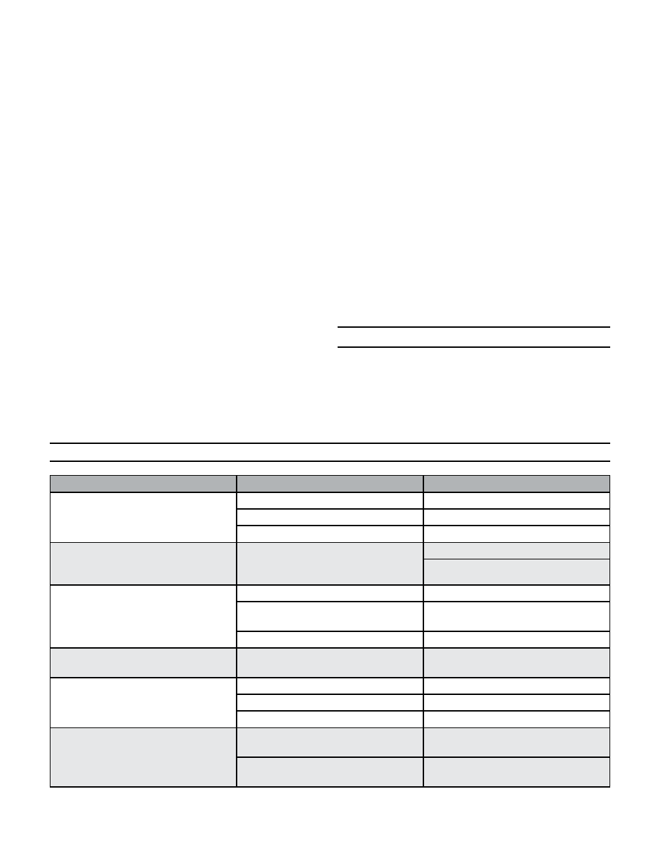
Symptom
Possible fault
Actions
Seat leakage through closed valve
Damage ball surface
Replace the ball
Damaged seats
Replace seats
Ball may not be closed fully
Check ball Open/Close setting
Irregular ball movement
Impurities between the ball and
seats or ball - body cavity and ball
seats
Flush the ball from inside
Clean the sealing surfaces and seats
Valve too hard to operate / valve
torque too high
Damaged seats
replace the seats
High application pressure /
temperature
Confirm the application pressure /
temperature rating
Foreign particles in valve
Clean the internals
Water hammer or noisy operation
Error in valve sizing, or
high velocity fluid flow
Confirm valve sizing with respect to
flow
Leakage through stem
Gland nut loose
Tighten gland nut
Damaged stem, stem sealing surface
Replace the stem
Damaged stem seal
Replace the stem seal
Leakage through body
Damaged O-ring or breakage of
gasket
Replace O-ring / gasket
Relaxtion of studs due to gasket
creep
Retighten the studs evenly in
crisscross manner
Troubleshooting