Sm87bg general arrangement – MEDC SM87BG User Manual
Page 3
all cables and cores should be correctly identified. Please refer to the wiring diagram provided with the product.
Ensure that only the correct listed or certified cable glands are used and that the assembly is shrouded and correctly earthed.
All cable glands should be of an equivalent NEMA/IP rating to that of the manual call point and integrated with the unit such
that this rating is maintained.
The internal earth terminal must be used for the equipment grounding connection and the external terminal is for a supplementary
bonding connection where local codes or authorities permit or require such a connection.
Once termination is complete, carefully push the cover assembly back onto the base avoiding damage to the mating surfaces.
Ensure that the retaining strap is not trapped between the mating surfaces and that the o-ring is correctly seated in its groove.
Ensure the retaining strap and wires are clear of the microswitch actuator and operating mechanism. Replace the 4 off M6
screws (5.0mm A/F hexagon key) into the holes in the cover assembly and tighten evenly. Ensure the maximum gap of 0.15mm
is maintained between the cover and the base once assembled.
3.0 OPERATION
The operating voltage of the unit is stated on the unit label. Please see the reference drawing supplied with each unit for details
of wiring and any fitted internal component values
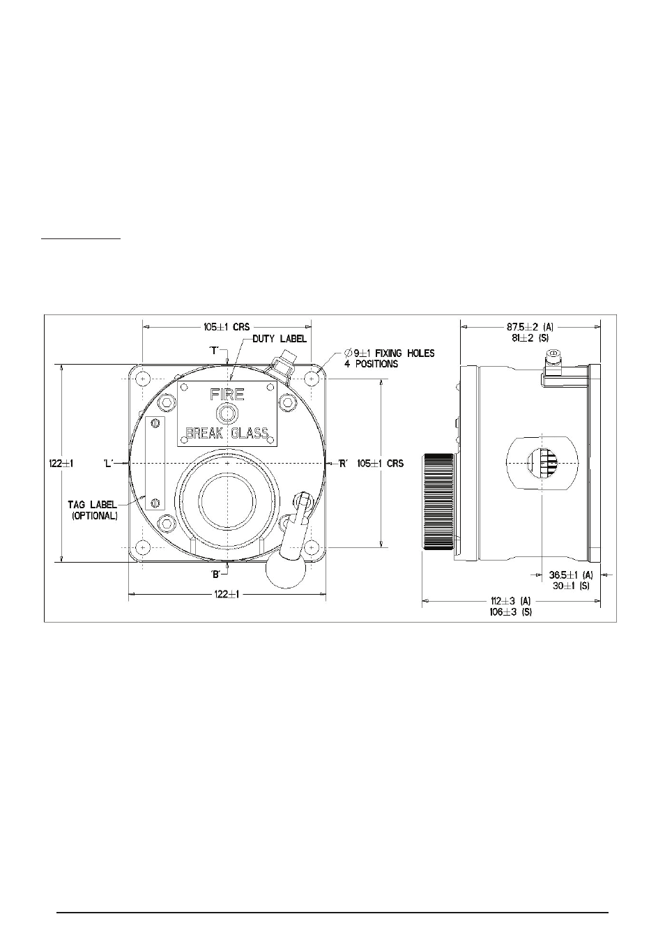
SM87BG GENERAL ARRANGEMENT
SM87BG units - operation
The unit is operated by breaking the glass element in the front of the cover using the hammer attached to the unit. If a lift flap
has been specified, this will need to be raised first to gain access to the glass element.
SM87BG units - resetting procedure
a. To replace the glass, a kit containing O-rings and glass is provided.
b. Unscrew and remove the circular bezel on the front of the unit.
c. Remove the original O-rings and glass and ensure the grooves in the bezel and cover are clean.
d. Fit the larger O-ring into the groove on the cover.
e. Fit the smaller O-ring into the groove on the underside of the bezel:-
i. Offer the O-ring up to the groove.
ii. Place thumbs of both hands side by side onto the O-ring
iii. Press the O-ring down into the groove circumference maintaining even pressure, forcing the O-ring into the groove.
08/11
© Cooper MEDC 2011