Multi-Contact MA260 User Manual
Page 4
Advanced Contact Technology
4 / 8
www.multi-contact.com
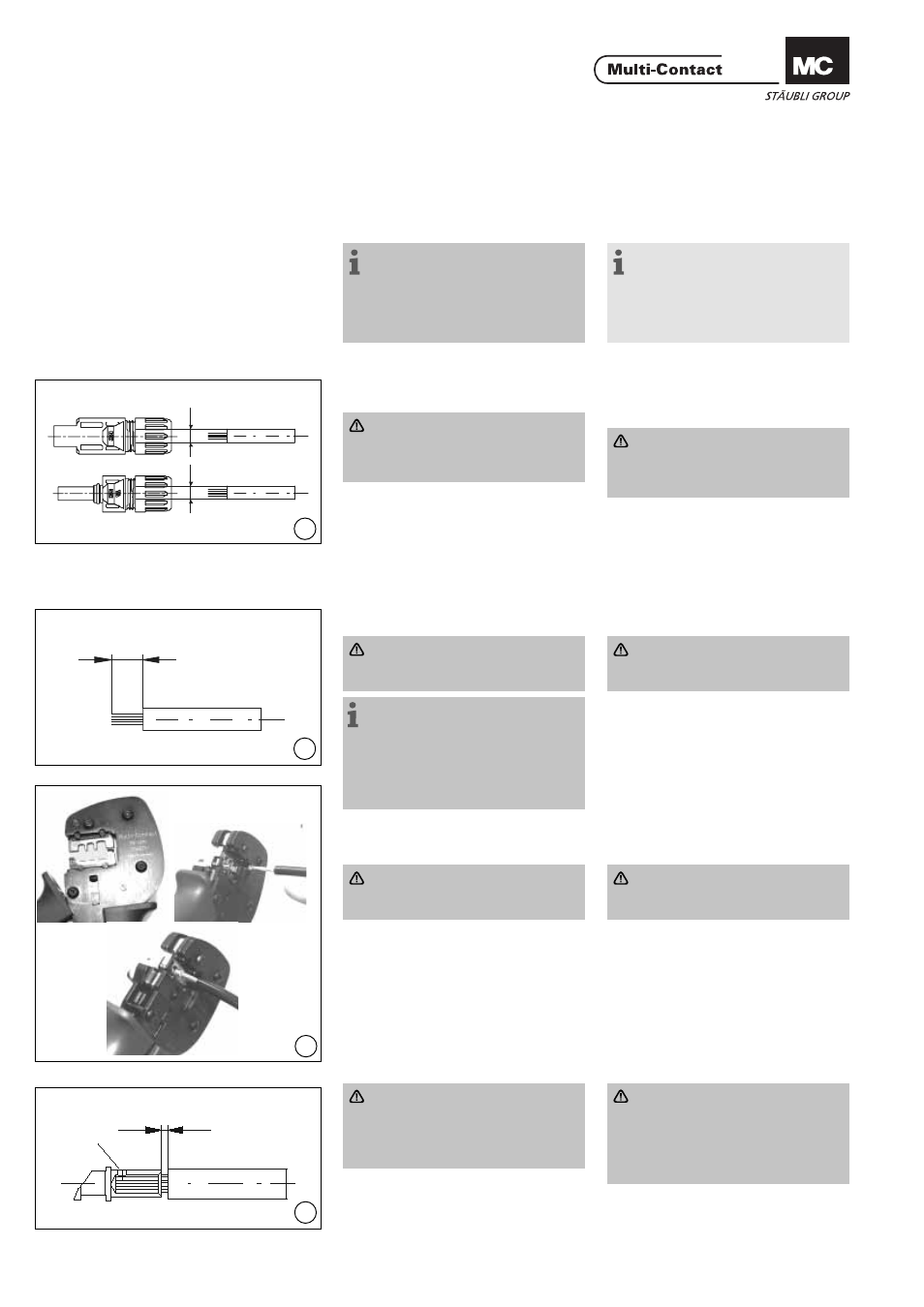
10
L= 6 - 7,5mm
S
max. 1 mm
12
9
A
A
11
Montaje
Assembly
Preparación de los cables
Cable preparation
Pueden conectarse cables de clase 5
o 6.
Cables with a strand construction of
classes 5 and 6 can be connected.
Nota:
No utilice cables oxidados o sin
revestimiento. Es aconsejable utilizar
conductores estañados. Los cables
solares AII MC cuentan con conduc-
tores estañados de alta calidad.
Note:
Use no uncoated or already
oxidised conductors. It is advantage
to use tinned conductors. All MC
solar cables have high-quality, tinned
conductors.
(ill. 9)
Se pueden conectar cables con sec-
ciones de 2,5 – 4mm² y 14 – 10 AWG.
Atención
Compruebe que el diámetro ex-
terior del cable corresponde al de
los pines macho y hembra.
Tipo: A = Ø del passacables
PV-K...T4/...6I:
3 – 6 mm
PV-K...T4/...6II:
5.5 – 9 mm
(ill. 9)
Cables with conductor cross section
from 2,5 - 4mm² resp. from 14 - 10
AWG can be connected.
Attention
Take care that the type of test
plug or test socket matches the
cable diameter (A).
Type: A = Ø range of cable
PV-K...T4/...6I:
3 – 6 mm
PV-K...T4/...6II:
5.5 – 9 mm
(ill. 10)
Pele el cable
Quite de 6 a 7,5 mm de aislante del
extremo del cable.
Atención:
Tenga cuidado de no cortar
ningún hilo.
Nota:
Para obtener instrucciones sobre
cómo utilizar los alicates pela cables
PV-AZM y cómo cambiar las hojas de
corte, consulte las instrucciones de
operación MA267 en www.multi-
contact.com
(ill. 10)
Strip cable insulation
1)
Remove 6 to 7,5 mm of insulation
from the end of the cable.
Attention
Take care not to cut individual
strands.
1)
For directions on the operation of strip-
ping pliers PV-AZM... and changing blade
sets, see operating instruction MA267 at
www.multi-contact.com
Engarce
Crimping
Importante
Utilice solo la herramienta de in-
serción MC3 PV-ES-CZM-16100!
Important
Use only the MC3 crimp insert
PV-ES-CZM-16100!
(ill. 11)
1. Coloque la parte metálica del pin
macho o hembra en la guía para la
sección de cable correspondiente.
2. Inserte el cable en la ranura de eng-
arce hasta el fi nal y fíjelo.
(ill. 11)
1. Place the metal part of the female
or male coupler in the guide for the
appropriate cross section.
2. Insert the wire into the crimping
sleeve as far as it will go. Hold the
wire in place in the sleeve.
(ill. 12)
Atención:
Todos los conductores deben ser
introducidos deben ser introdu-
cidos en el orifi cio S dejando una
distancia máxima visible de 1mm
3. Cierre completamente la herramien-
ta de engarce.
(ill. 12)
Attention
All strands of the wires must be
correctly inserted into the bore-
hole and visible in sight hole S.
The max. distance of 1mm must
not be exceeded.
3. Completely close the crimping tool.