Ah.fs, 9 alarm group (g.alm) – Precision Digital PD554 User Manual
Page 37
.
.
.
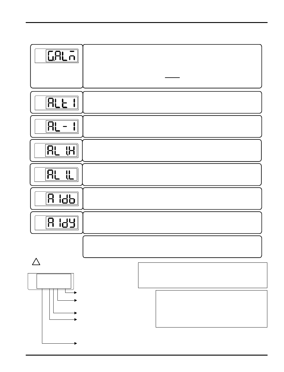
5.9 Alarm Group (G.ALM)
Press SET/ENT key to select the alarm group. (Refer to parameter map in section 3.)
The parameter to set the type of alarm to be set for alarm 1.
The types of alarms selectable are shown in Table 3: Alarm Selection.
PV
The parameter to set the alarm trigger point for the alarm set in ALT1.
This parameter displays if a high, low, or high and low limit alarm was selected for ALT1.
PV
PV
The parameter to set the dead band (Hysteresis) of alarm 1.
PV
The parameter to set the delay time before of alarm 1 is triggered.
PV
Note: The menus for alarm 2 and 3 are the same as alarm 1.
This establishes the high d eviation range to trigger the alarm of deviation. This parameter
displays if a deviation alarm was selected in ALT1.
This establishes the lo w deviation range to trigger the alarm of deviation. This parameter
displays if a deviation alarm was selected in ALT1.
PV
PV
G.AT
Q G.PID Q PWD Q G.CTL Q G.IS Q G.DO
K R
G.COM
Q G.RET Q G.ALM Q G.OUT Q G.IN
ST
ST
ST
ST
ST
ST
ST
ST
ST
ST
T
Standby Operation:
The alarm will n ot trigger if the alarm condition
occurs during the following activities...
- during power-up
- the set point is changed
- the type of alarm is changed
Alarm Output Settings:
- Forward: Relay energized in alarm condition
- Reverse: Failsafe operation. Relay energized during normal
operating conditions
SP
S indicates standby operation
F for forward operation
r for reverse (failsafe) operation
Alarm Types and LED Display
Decimal point always displayed
H indicates a high alarm
L indicates a low alarm
o for outside range of deviation band
I for inside range of deviation band
A indicates an absolute value alarm
d indicates a deviation alarm
?
NOTE
AH.FS
PD550 Series Nova Programmable Process and Temperature Controller
Instruction Manual
37