Diameter, Height lunar – RISCO Group Industrial LuNAR User Manual
Page 2
Starting to Use the RC
NO LINK, TRY TO
CHANGE POSITION
On
Introduction
The Remote Control (RC) device is a unique bi-directional infrared remote control
tool used to easily control and test the Industrial LuNAR detector. On one hand
the RC can perform a self-test on the detector and receive data and status reports
On the other hand it can send information to the detector and update the detector’s
parameters. The RC is powered by two lithium CR123 batteries.
Enabling RC Communication with the LuNAR
WARNING
When the LuNAR is configured to the Relay mode the following steps
must be performed: (for more information, refer to the Industrial LuNAR
Installation Manual).
1) Verify that dipswitch 6 on the LuNAR PCB is in “OFF” position.
2) Verify that dipswitch 7 on the LuNAR PCB is in “ON” position.
3) Apply “0” level to the “RC” terminal on the LuNAR terminal block (usually
performed via a utility output on the control panel).
For the Bus mode the following steps must be performed: (for more
information, refer to the Industrial LuNAR Installation Manual and Industrial
LuNAR Instructions for ProSYS programming).
Turn DIP switch 7 “OFF” after installation and when leaving the site for
security reasons. This will prevent unauthorized use of a remote control
unit that may be used to disable the detector.
1) Verify that dipswitch 6 on the LuNAR PCB is in “ON” position.
2) Enter the Walk Test Mode, in the ProSYS, which enables all the Industrial
LuNAR detectors on the bus to communicate with the RC .
RC Key Functions
Figure 1: RC Key Functions
* Followed by pressing
button
Select
Increases MW
sensitivity (greater
range)*
Decreases MW
sensitivity (smaller
range)*
Turns On/Off the Remote
Control device (toggled operation).
Accepts current selection
and transmits it to the
LuNAR.
Disables ACT mode*
Enables ACT mode*
Enables the LEDs operation*
Activates LuNAR self-test.
The following info is displayed on the LCD:
* Input voltage level,
* MW signal and noise level,
* PIR CH1/CH2/CH3 DC signal level,
* PIR CH1/CH2/CH3 noise level
Pressed to scroll up/down
a list
Disables the LEDs operation*
LCD display: Visually
displays the data
information
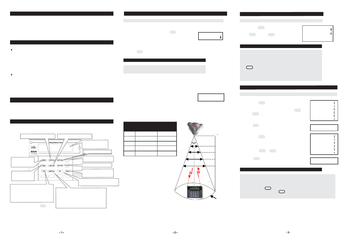
To use the RC, perform these steps:
1. Turn on the RC by pressing the button.
The following display appears each time the LuNAR
is activated:
2. If required, use the RC arrows to scroll down the list
and select your desired language.
3. Press
to confirm your selection.
Select
NOTE:
Upon power off, the last selected language is saved and will
be used upon next power up.
4. Point the RC infrared towards the LuNAR. Stand within
the 36° zone (see below) for optimum reception. The
effective RC reception distances and mounting heights
are shown below.
5. If the LuNAR does not respond, it is probably due to
a link failure; change RC position until the link is
achieved.
“No link” state message may appear if the LuNAR is
not enabled for RC communication (see “Enabling RC
Communication with the LuNAR” section).
ACTION
LCD DISPLAY
A
B
C
D
E
2.7m - 4.9m
4.9m - 6.2m
6.2m - 7.8m
7.8m - 8.6m
8.6m
1.6m
3m
3.7m
4.7m
5.2m
Diameter
Mounting
Height
Point
MW set to XXX
ACT is enabled/disabled
LED is enabled/disabled
Software Version XXX
No trouble/trouble
Info
>
>
1.
Press the button to get the desired
info; the info appears on the LCD. Use the
up or down arrows to scroll
up/down the list and view the desired info.
Getting Information
ACTION
LCD DISPLAY
1.
Press the button to increase the MW
sensitivity. Select the desired sensitivity by
scrolling up/down the list, using the up or
down arrows.
2. Press to confirm and transmit your selection.
The following message appears:
3. Press the button to decrease the MW
sensitivity.
Select the desired sensitivity by scrolling
up/down the list,
using the or down arrows.
4. Press to confirm and transmit your selection.
The following message appears:
MW-
Select
MW+
Settings were
updated
>
>
Settings were
updated
Select
Select
1. Selecting the “SET TO TRM” option from the displayed list of options,
implicates that the MW sensitivity will be set to the level defined by the
trimmer on the PCB.
2. If after pressing button you receive the message ”No link try to
change position”, pressing button again will transmit once more
the last selected parameters.
NOTES:
Gets info from the LuNAR as follows:
* MW sensitivity
* LEDs status operation
* ACT mode
* SW version
* Trouble indication
REMOTE READY
ENGLISH
NOTES:
1. There are 3 optional trouble messages:
*MW trouble: Trouble in the MW channel.
*PIR trouble: Trouble in the PIR channel.
*PS trouble: Trouble in the detector input voltage
2. If button was not pressed, an “Unknown
MW/ACT/LEDs” message will appear on the LCD while
trying to change the settings of these parameters.
(MW/ACT/LEDs).
MW set to XXX
Set it to TRM
Set it to MAX
Set it to 85%
Set it to 65%
Set it to 50%
Set it to 25%
Set it to MIN
ACTION
LCD DISPLAY
Increasing/Decreasing MW Sensitivity
MW set to XXX
Set it to TRM
Set it to MAX
Set it to 85%
Set it to 65%
Set it to 50%
Set it to 25%
Set it to MIN
Info
Select
>
>
A
36
0
B
C
D
Diameter
E
Height
LuNAR
Each of the RC keys has a special functionality as explained below: