Voice module components, Channels – RISCO Group ProSYS EV User Manual
Page 7
Voice Module Installation Guide 7
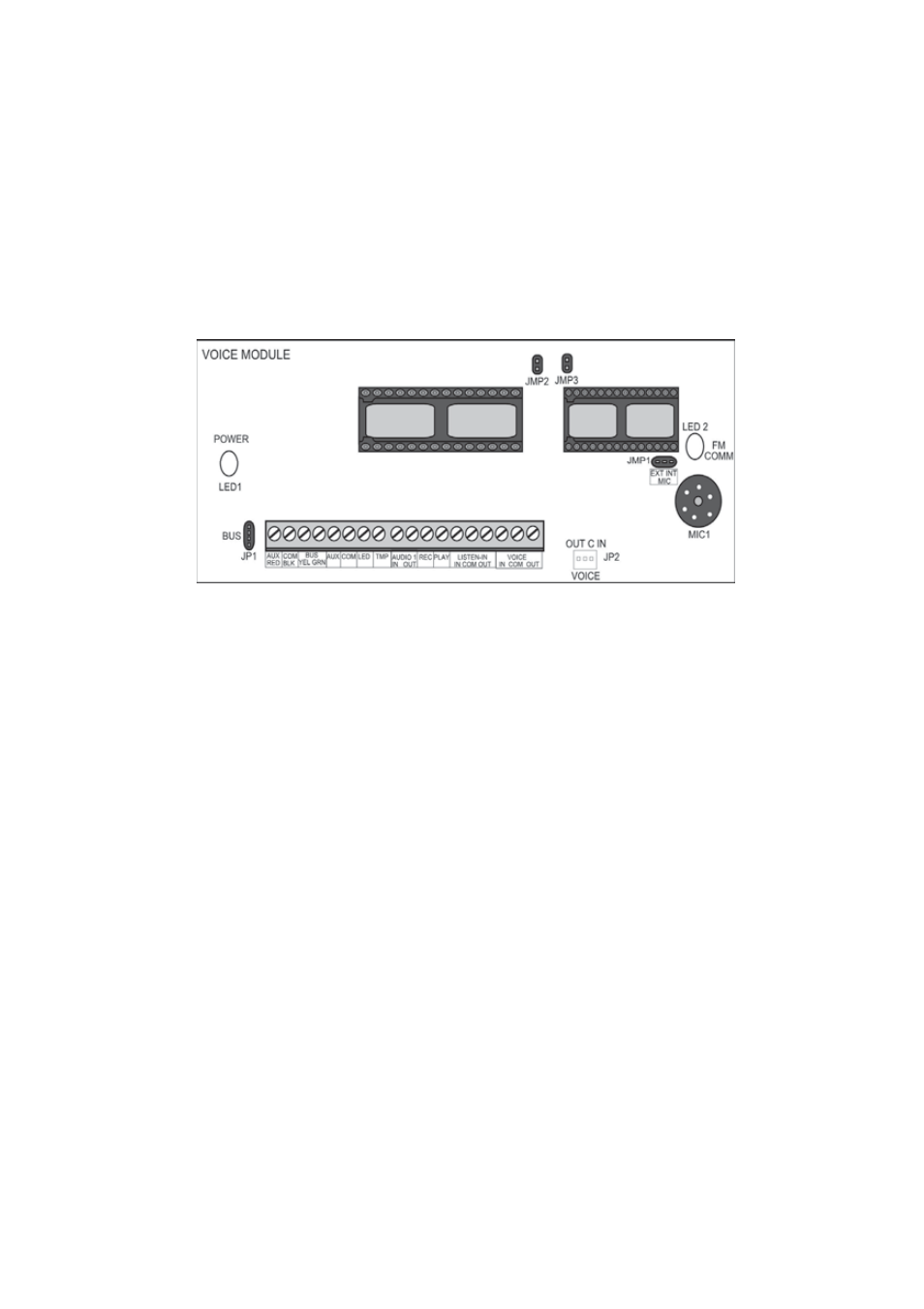
2. Voice Module Components
The following diagram shows the layout of components in the
Voice module:
The following is a list of components in the Voice module:
Ø
Channels, described on page 7.
Ø
LED Indicators, described on page 9.
Ø
Jumpers and Connectors, described on page 10.
Channels
The Voice module contains the following three channels, which are
located on the voice module PC board:
Ø
Audio Channel: Used for recording and announcing
messages. When recording messages for UOs, zones,
partitions and common message it is recommended to
connect to a Message Box Unit (MBU) that has buttons
to this channel. When the recording or message
announcement is performed, all MBUs work in parallel
and all microphones connected to this channel are
activated.