Retrotec Triple Fan Blower Door System Setup with DM-2 User Manual
Page 4
Page 4 of 6
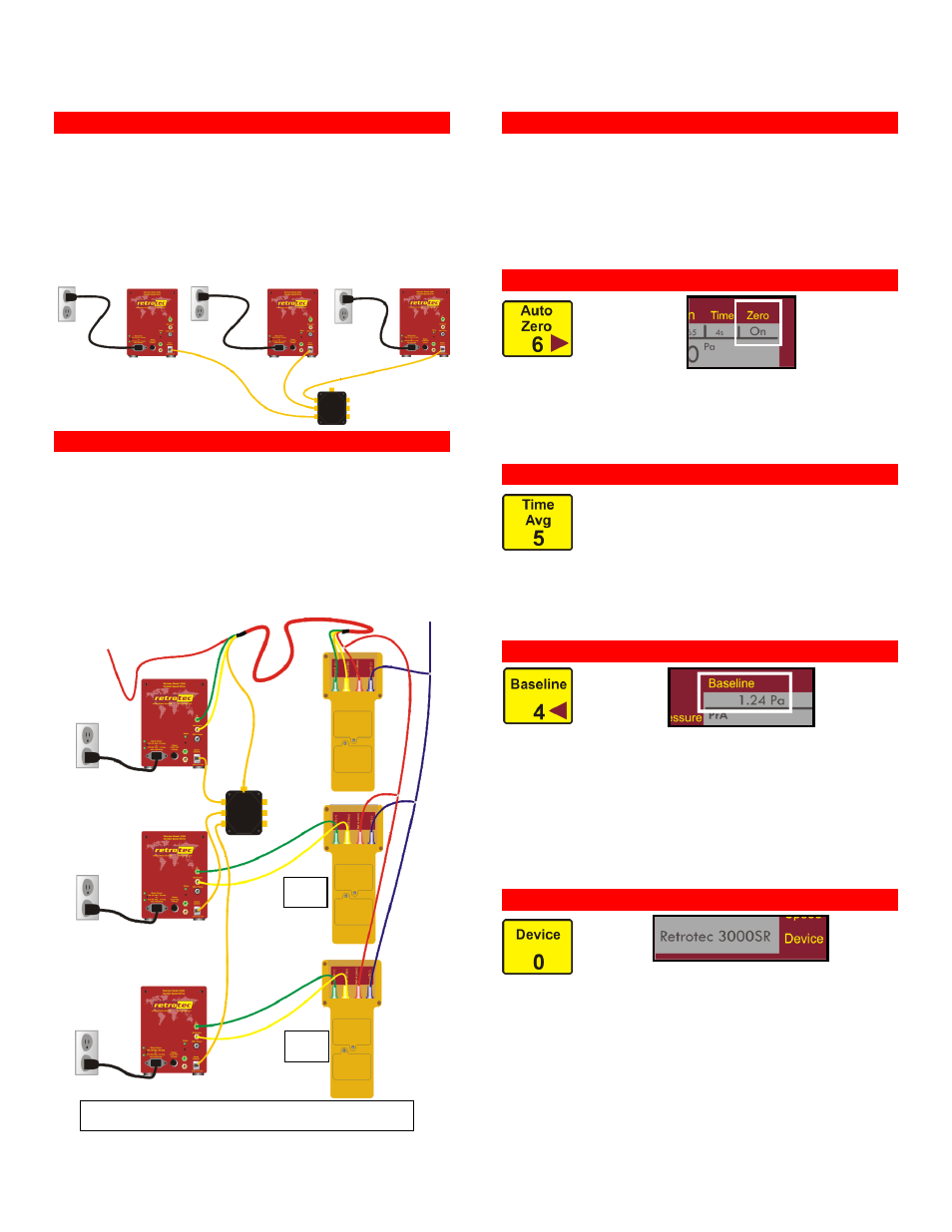
13 Connect the variable speed drives
13.1 Plug each drive into a 20 amp outlet (not GFCI),
on an independent circuit, to avoid tripping the
breaker.
Tip A stove outlet is usually on an independent circuit.
13.2 Connect each drive unit to any port on the splitter
box using the control cables if manually controlling
fan speed.
14 Connect DM-2 #2 and #3
14.1 Connect DM-2 #2 and #3 to the remaining two
variable speed drives.
14.2 Connect the yellow and green tubes between
Channel A of DM-2 #2 and Drive #2.
14.3 Connect the yellow and green tubes between
Channel A of DM-2 #3 and Drive #3.
14.4 If fan control will be handled through FanTestic
software, connect the control cables directly to the
drive units, as shown on the first page.
15 Begin automatic test
15.1 If using FanTestic software, begin the test at this
point.
15.2 Follow the instructions as laid out in the FanTestic
User Manual, or as they appear on screen.
15.3 If conducting the test manually, continue on to
step 16.
16 Zero gauges
16.1 Press [Auto Zero]. When “On” is displayed, the
gauge will zero itself every 8 seconds.
16.2 This needs to be done on all gauges.
Tip Normally, Auto Zero should be left “On”; turn off to save
battery power.
17 Set time averaging
17.1
Press [Time Avg] as needed, until
“PrA” varies by less than 1Pa. Windy
conditions will require a longer time
averaging.
17.2 Wait for twice the time average setting before
taking a reading.
Tip 1s, 2s, 4s, 8s updates every 1 second(s),
10s, 20s, 1min, 2min updates every 10 seconds.
18 Measure bias pressure
18.1 Prior to each test, with the fans covered, press
[Baseline] on all gauges to begin averaging the
bias pressure.
18.2 Press [Enter] after about 60 seconds to capture
the bias pressure reading.
18.3 After each test, press [Exit] to clear the baseline.
Note The value displayed under “Baseline” will offset the
influence of bias pressure on the pressure reading.
19 Set fan model on DM-2
19.1 Press [Device] on DM-2 #1 until “Retrotec
3000SR” is displayed.
19.2 The 3000SR fan model has two pressure tubes
attached. If there is no reference port on the fan,
set the Device to “Retrotec 3000”.
See: QuickGuide-DM2MkII
#2
#3
DM-2 control setup for common fan control