Member of jost-world, Technical data, Series ro – ROCKINGER RO 560 User Manual
Page 4
Characteristic value for public road
part no.
C E N T R A L - A X L E T R A I L E R
hand lever
hand lever
size
hole pattern
maximum
maximum
maximum static
maximum
weight
upwards
downwards
(mm)
D-value*
1
(kN)
Dc-value*
1
(kN)
vertical load*
2
(kg)
V-value*
1
(kN)
(kg)
560A6000*
560B6000*
6
160 x 100
190
106
1000
45,6
38
* interim plate part no. 71053 upon requirement usable
Characteristic values for agriculture and forestry
part no.
admissible
C E N T R A L - A X L E T R A I L E R
hand lever
hand lever
size
hole pattern
gross weight
maximum
maximum static
admissible
weight
upwards
downwards
(mm)
of tractor (t)
Dc-value*
1
(kN)
vertical load*
2
(kg)
gross weight (t)
(kg)
560A6000
560B6000
6
160 x 100
14
0
93,6
2000*
3
32
38
with interim plate part no. 71053
14
106
1000
32
41
Upgrade kits:
x Mechanical remote operation
part no. 70962
x hydraulic remote operation
part no. 70999
x electropneumatic remote operation
part no. 70844
x In-cab status indicator
part no. 70936
x Drawbar turn angle warning system
part no. 70935
*
1
Calculation see list A, B
*
2
Recommendation: with central-axle tailers the static vertical load should be at least
**
4 % of the towed load to avoid a negative vertical load which can cause damage.
*
3
with individual confirmation for individual
*
3
homologation
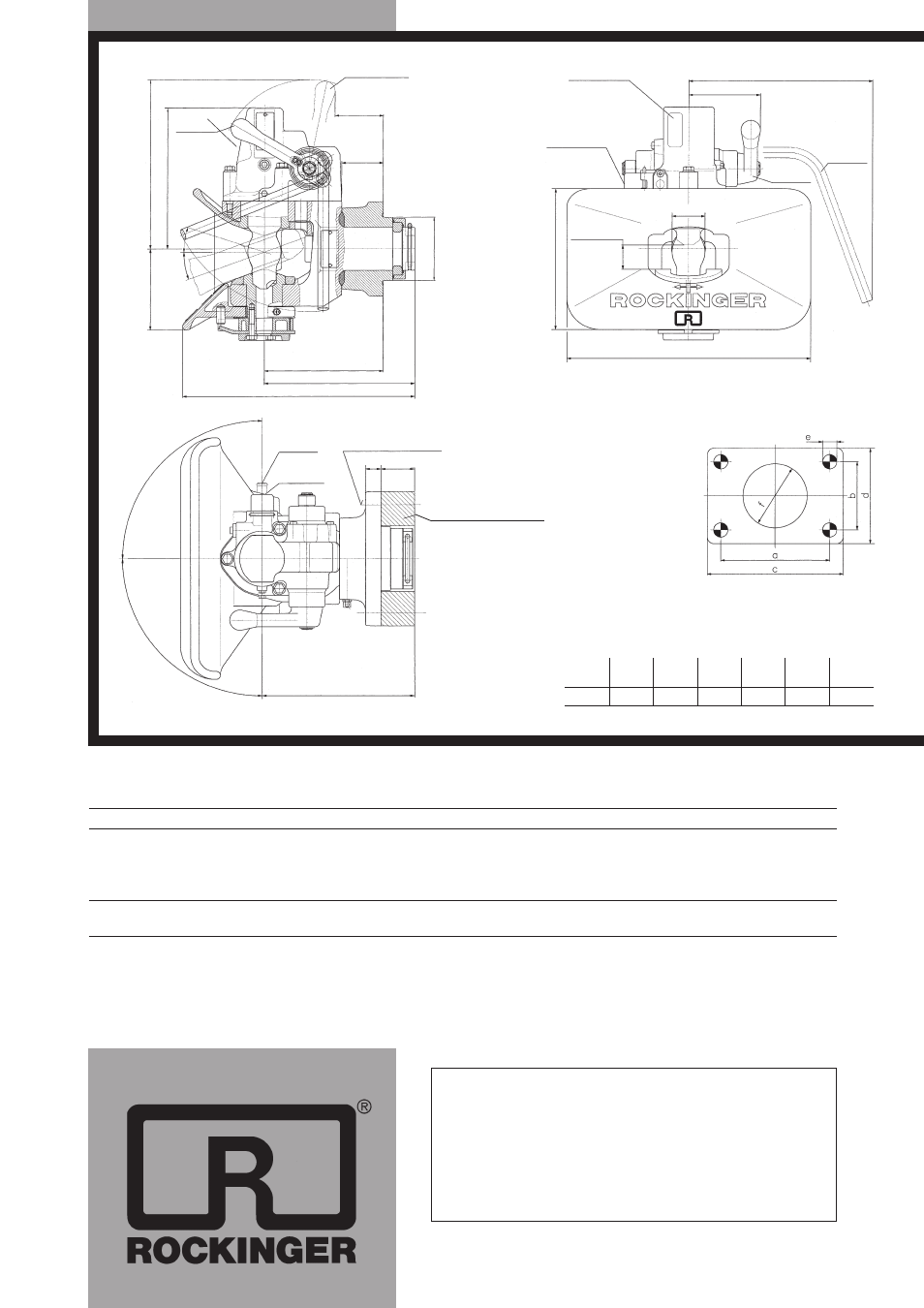
informative sticker
for ”safety
indicator“
dimension
for releasing safety
mechanism
for drawbar
eye
coupling
closed
hand lever
upwards
hand lever
downwards
l48,7
175,4
+0,6
–0,5
225,4
+0,8
–0,7
360 +10
21
0e
10
37
r
2,5
270
e5
106
e5
coupling
closed
coupling open
71
e10
61,4
e1
l
94
r
0,2
12
0e
5
250 max.
200
+10
m
in
.2
0h
m
in.
2
0h
222
+1,5
bolt heads for attachement
on coupling head side
342
e5
23
e1,2 50e0,2
coupling
open
coupling
closed
m
in
. 9
0h
centre line
of drawbar eye
m
in
. 9
0h
Technical
data
size
a
b
c
d
e
f
(mm)
(mm)
(mm)
(mm)
(mm)
(mm)
6
160
100
200
140
21
94
flange size to 94/20/EC
Series RO
i
560
Type 560 U 6 e1 00-0404
class C 50-X
for drawbar eyes 50 DIN 74053,
EC 94/20 class D, ISO 1102,
drawbar eye RO
i
57005
interim plate
upon requirement usable
not with vertical load S = 2000 kg
in the agriculture or forestry
Repair instructions and parts list available on request !
Available from your specialist dealer:
Member of JOST-World