Mounting, Adjusting the maximum audio level, Technical references and support – Rosen Aviation 0700-001 : Headphone Distribution Amplifier User Manual
Page 8
Rosen Aviation
Document Number: 100318
Revision: B
Date: 05/19/15
Template: 4.2.3-6-FM; Revision A; 16 May, 2005
Page 8 of 13
5. MOUNTING
Mount the Headphone Distribution Amplifier in any orientation using the four mounting slots in the
flange brackets on the exterior housing. Refer to Note 3 on the Outline and Installation Drawing.
6. ADJUSTING THE MAXIMUM AUDIO LEVEL
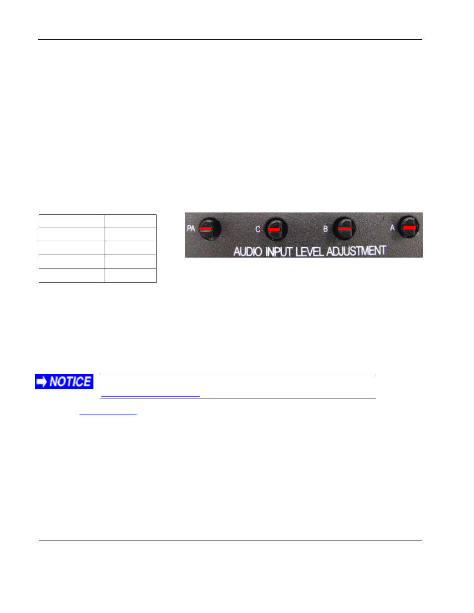
The factory defaults for the potentiometers, as shown in Figure 4, are set to line level. This means
that the signal coming out of the amplifier is equal to the signal going in. Adjust each knob
individually to set the maximum audio level for each input.
After establishing the maximum audio level, use the potentiometers to match the line levels for the
audio sources to provide a consistent volume when switching input sources. To lower the audio
level, turn the knob counter-clockwise; to raise it, turn the knob clockwise.
Table 5 Audio input level controls
Potentiometer
Control
A
Channel A
B
Channel B
C
Channel C
PA
Pilot mic
Note: To avoid popping when you power the system on and off, do not reverse or interconnect the
ground and return lines.
7. TECHNICAL REFERENCES AND SUPPORT
The Outline & Installation drawing is also available at
From the
home page, select Support Drawings and Pinouts, and look for the
product name under the Accessories category.
Figure 4 Line-level positions for potentiometers