Table 2-5. input and output connectors, 3 ac input requirement – KEPCO MAT Full Rack MAT 6V, 15V, 25V AND 36V MODELS User Manual
Page 21
2-4
MAT 6V/15V/25V/36V/ 022300
2.3
AC INPUT REQUIREMENT
The Power Module operates on a single phase, 115 Va-c nominal line. The Power Module can
also be connected to 230 Va-c by the following procedure:
CAUTION: The following procedure is only authorized to be performed by a trained ser-
vice technician.
1.
Disconnect the AC Input power from the MAT Power Module and remove the six screws
from the Front Panel, see Figure 2-1. Place the panel face down on a padded surface to
avoid damage. With the front panel removed, locate the barrier terminal block mounted on
the chassis.
NOTE: Do not move the wires connected to the barrier strip, they are properly placed for both
115 Va-c and 230 Va-c operation.
2.
Figure 2-3A shows the barrier terminal block set to 115 Va-c
operation. Remove the jump-
ers on the barrier strip connecting terminals 2 to 3, and terminals 4 to 5.
3.
Place a jumper between terminals 3 and 4. For 230 Va-c the barrier strip appears as in Fig-
ure 2-3B.
4.
Place prominent labels at the front and rear panel indicating the unit is wired for 230V a-c
operation.
To return to 115 Va-c operation reverse the procedure. Remove the jumper in step 3 and replace
the jumpers in step 2. Indicate unit is wired for 115V a-c in step 4. Replace labels to indicate unit
is wired for 115V a-c.
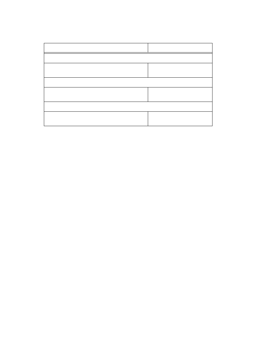
TABLE 2-5. INPUT AND OUTPUT CONNECTORS
CHASSIS MOUNT
MATING PLUG
AC INPUT CONNECTOR (MIL STD CONNECTOR, MS TYPE OR EQUIVALENT)
MS3102A16-10P
MS3108A16--10S
(KEPCO P/N 143-0331)
DC OUTPUT CONNECTORS (MIL STD CONNECTOR, MS TYPE OR EQUIVALENT)
M3102A28-5S
MS3106A28-5P
(KEPCO P/N 142-0358)
DIGITAL BUS CONNECTOR
DIN 41524 (SOCKET)
DIN 41524 (PLUG)
KEPCO P/N142-0308