Connector, simplified diagram -19 – KEPCO RA 19-1U Operator Manual User Manual
Page 35
Advertising
RA 19-1U 020413
2-19
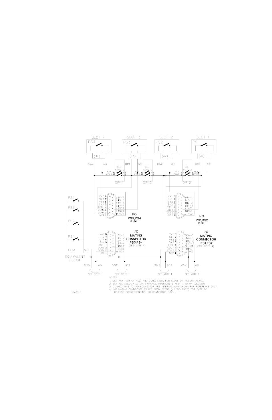
2.4.4.1.2 CLOSE ON FAILURE USING EXTERNAL WIRING AT I/O MATING CONNECTOR
Close on failure for multiple power supplies can be accomplished by wiring N.O. and COM in
parallel at the I/O mating connector. DIP switches associated with slots included in the alarm cir-
cuit must have positions 6 and 7 set to OFF (open). The failure indication (short circuit) will be
present across any pair of N.O. and COM lines. Figure 2-13 is a simplified diagram illustrating a
close on failure alarm configuration for four power supplies using external wiring at the I/O mat-
ing connector.
FIGURE 2-13. CLOSE ON FAILURE ALARM CONFIGURATION USING EXTERNAL WIRING AT I/O MATING
CONNECTOR, SIMPLIFIED DIAGRAM
Advertising