Maintenance procedures, Required inspections and adjustments (con’t.) – SAF-HOLLAND XL-FW421-02 XA-201-A-80-L Air Release User Manual
Page 7
Improper adjustment can cause
improper locking of the fifth
wheel. If the fifth wheel does not operate
properly, DO NOT USE IT! Repeat the above
adjustment procedures or contact your local
Holland Representative for assistance. Using an
improperly adjusted fifth wheel could result in an
improper couple and tractor seperation which may
cause death or serious injury to others.
Adjustment – Locking Mechanism
1. Using ONLY a Holland TF-TLN-5001 Lock
Adjustment Tool, lock the fifth wheel.
2. Check the plunger – it must be visible
behind the lock and engaged on both
steps, as shown in Figure 3A. If the plunger is
not visible or not engaged on both steps (Figure
3B), turn the adjustment bolt counterclockwise
1/2 turn, then try to lock the locks again.
3. Check the release handle – it must be fully
retracted and the handle lock notch must be
behind the rib as shown in Figure 3C.
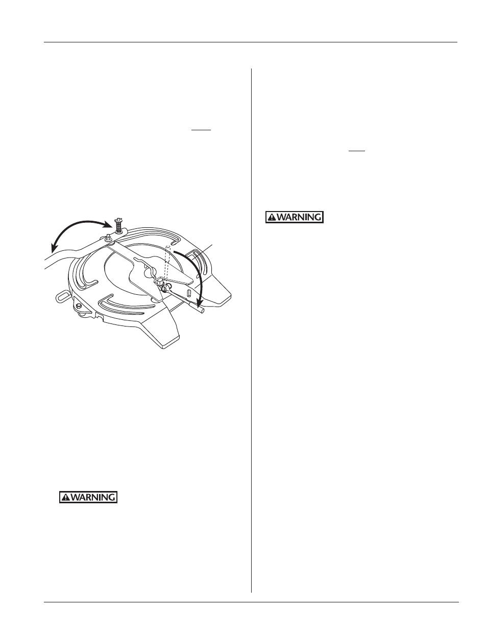
4. Using a 15/16˝ socket, tighten the locks by
turning the lock adjustment bolt clockwise 1/4
turn at a time. Remove the socket wrench from
the bolt and rotate the lock adjustment tool, as
shown in Figure 4, to check for resistance
between the lock and lock adjustment tool.
5. Continue to alternate tightening (clockwise) the
adjustment bolt 1/4 turn at a time, removing
the socket wrench, and rotating the lock
adjustment tool until you feel resistance against
the lock adjustment tool. Once you begin to feel
resistance, STOP!
6.
7. Loosen the adjustment bolt counter-clockwise
TWO FULL TURNS (ie: one full turn is 360°
rotation of socket). The lock is now properly
adjusted.
8. Verify this adjustment by locking and
unlocking several times using the Lock
Adjustment Tool; check for proper locking (See
Figure 3A and Figure 3C).
9. If there is a large amount of fore and aft
movement with the adjustment tool when
verifying adjustment, check to make sure the
lock is engaged in both steps (Figure 2).
If the lock is only engaged on one step, repeat
Step 2 (above), of the Adjustment Procedure until
the lock engages on both steps. (See Figure 3A.)
2
ROTATE
1
TIGHTEN
Figure 4
7
MAINTENANCE PROCEDURES
Required Inspections and Adjustments (con’t.)
At this point, the fifth
wheel is OVERADJUSTED and
NOT useable. Using an improperly adjusted
fifth wheel could result in an improper couple
and tractor seperation which may cause death
or serious injury to others.
XL-FW421-02