Instructions for the installer – DE DIETRICH DTG1195X User Manual
Page 19
7
room ventilation rules where appliance is installed
make reference to the legislation, in conformity
with the local regulations.
FOR THE U.K. ONLY
The room containing this hotplate should have an
air supply in accordance with BS 5440: Part 2:
1989.
-All rooms require an openable window, or
equivalent and some rooms will require a
permanent vent a well.
-For room volumes up to 5 m
3
an air vent of 100cm
2
is required.
-For room volumes between 5 m
3
and 10 m
3
an air
vent of 50 cm
2
is required.
-If the room is greater than 5 m
3
and has a door that
opens directly to the outside, then no air vent is
required.
If there are other fuel burning appliances in the
same room BS 5440: Part 2:1989 should be
consulted to determine the air vent requirements.
Gas connection
Make sure that the appliance is adjusted for
the gas type available (see the label under the
appliance). Follow the instructions indicated in
the chapter “gas
transformations
and adjustments”
for the possible
adaptation to
different gases.
The appliance
m u s t b e
connected to the gas system by means of stiff metal
pipes or flexible steel pipes having continuous
walls, in compliance with the regulations in force.
Some models are equipped with both cylindrical A
and conical B connectors for gas supply (fig. 7).
Please select the type which is correct for the
supply concerned.
The connection must not stress the gas ramp.
Once the installation is over, check the
connection seal with a soapy solution.
Electric connection
The connection to the electric grid must be carried
out by qualified personnel and in conformity with
the regulations in force.
The voltage of the electric system must correspond
to the value indicated in the label under the
appliance. Make sure that the electric system is
provided with an effective ground connction in
compliance with the regulations and provisions of
the law.
Grounding is compulsory.
If the appliance is not equipped with a plug, apply
a standardized plug to the power supply cable.
This device must be at a suitable opening distance
from the contacts in order to allow the entire
disconnection in case of overvoltage category III,
in accordance with installation rules.
GAS TRANSFORMATIONS AND ADJUSTMENTS
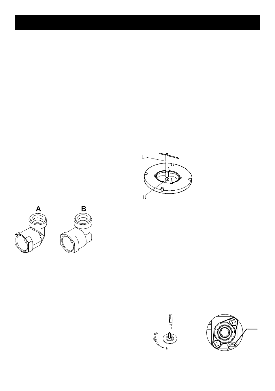
Replacing the nozzles
If the equipment is adjusted for a type of gas that is
different from the one available, it is necessary to
replace the burner nozzles.
The choice of the nozzles to replace must be
made according to the table of the “technical
characteristics” as enclosed.
Act as follows:
-
Remove the racks
and burners.
-
B y m e a n s o f
a straight spanner L,
unscrew the nozzle U
(fig.8) and substitute it with
the corresponding one.
-
Tighten the nozzle
strongly.
Adjusting the burners
The lowest flame point must always be properly
adjusted and the flame must remain on even if
there is an abrupt shift from the maximum to the
minimum position.
If this is not so, it is necessary to adjust the lowest
flame point as follows:
-start the burner up;
-turn the tap up to the minimum position (small
flame);
-remove the knob from the tap rod;
-introduce a flat-tip screwdriver C in the hole of
control panel of the tap (fig. 9) and turn the by-
pass screw V (fig.9/A) up to a proper adjustment
of the lowest flame point.
Fig.9
Fig.9/A
As regards G30 gas burners, the by-pass screw
must be tightened completely.
V
INSTRUCTIONS FOR THE INSTALLER
Fig.8
Fig.7