Avago Technologies ACPL-C790-000E User Manual
User guide, Isolation amplifi er evaluation board user manual
ACPL-C79B, ACPL-C79A & ACPL-C790
Isolation Amplifi er Evaluation Board User Manual
User Guide
Quick-Start Guide
Once visual inspection is done to ensure that the Evaluation Board is received in good condition, the Evaluation Board
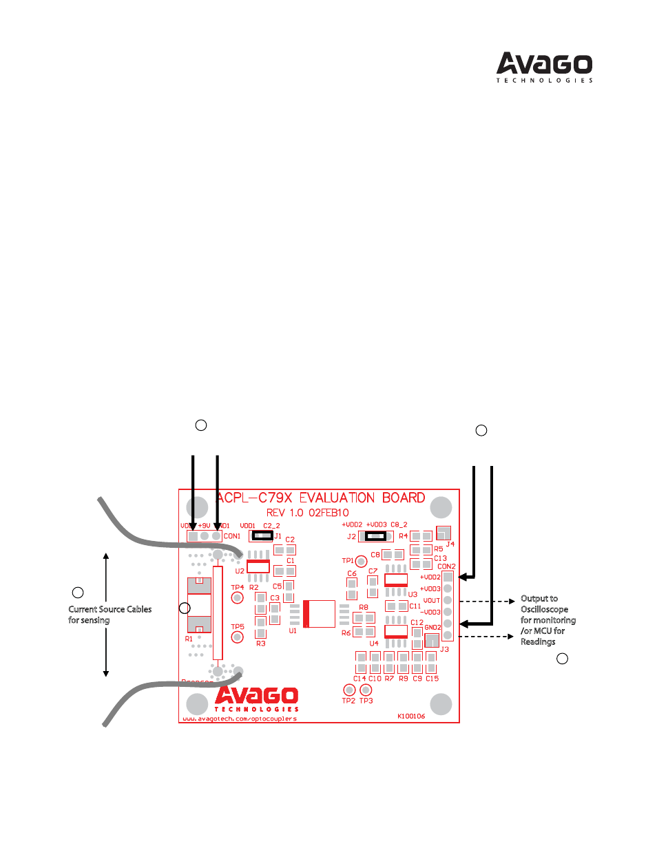
can be powered up in just 3 simple steps according to Figure 1 as shown:
1. Select either one of the provided sensing resistors (10mΩ or 15mΩ), or user’s own sensing resistor and mount it
(through soldering) on pads provided for R1 on the Evaluation Board;
2. Connect the necessary power supplies and current source as shown:
a. Connect 1st isolated 5V DC supply (DC Supply 1) to connector CON1 as shown;
b. Connect a 3.3V DC supply (DC Supply 2, can be non-isolated) to connector CON2 as shown;
c. Connect, through soldering, the required input current source (for sensing) cables as shown;
3. Supply the input current (subject to a maximum signal level of 250mVpp, or ±125mVdc across resistor R1) through
the cables (as shown in 2c) and monitor the output through an oscilloscope.
Figure 1. Default Test Setup of Evaluation Board
+5V
Gnd1
DC Suppl
y
1
+3.3V
Gnd2
DC Suppl
y
2
Current Source Cables
for sensing
Output to
Oscilloscope
for monitoring
/or MCU for
Readings
1
2a
2b
2c
3
1