Schematics, Board description, Using the board – Avago Technologies ACPL-C790-000E User Manual
Page 2: Figure 2. schematics of acpl-c79x evaluation board, Figure 3. top view of acpl-c79x evaluation board
2
Schematics
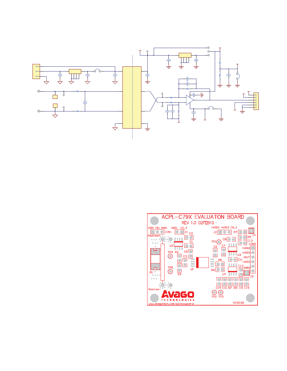
Schematics of the Evaluation Board are as shown in Figure 2.
J1
C5
100nF
GND1
V DD1
1
V in+
2
V in-
3
Gnd1
4
Gnd2
5
V out-
6
V out+
7
V DD2
8
U1
ACP L-C79X
C2
100nF
GND1
1
2
3
6
7
8
U2
LM78L05ACM
GND1
C1
100nF
GND1
1
2
3
CO N1
CO N1X3
GND1
Batt-/Gnd1
9V Batt+
V dd1
C3
22nF
R2
10R, 1%
R3
10R, 1%
Rsense-
R1
GND1
GND1
Rsense+
GND2
C6
100nF
TP1
GND2
C7
100nF
1
2
3
6
7
8
U3
L78L33ACD 13TR
GND2
C8
100nF
GND2
R4
1K , 1%
+V dd3
2
3
6
4
7
+
-
U4
OPA237UA
R6
10K , 1%
R8
10K , 1%
R7
10K , 1%
C10
68pF
C11
0.1uF
GND2
C12
0.1uF
J3
GND2
GND2
-V dd3
R9
10K , 1%
V ref
C9
68pF
TP3
TP2
GND2
R5
1K , 1%
C13
10uF
J4
GND2
GND2
GND2
V ref
+V dd2
+V dd3
-V dd3
GND2
+V dd2
C14
NM
C15
NM
1
2
3
4
5
6
CO N2
6PIN HEADER
J2
TP4
TP5
Figure 2. Schematics of ACPL-C79X Evaluation Board
Board Description
The ACPL-C79X evaluation boards (shown in Figure 3),
can accommodate either a ACPL-C79B(0.5% tolerance),
ACPL-C79A(1% tolerance), or ACPL-C790(3% tolerance)
device on U1, to demonstrate the high linearity and low-
off set capability of Avago’s Isolation Amplifi er over a wide
range of input current conditions. It allows a designer to
easily test the performance of the high-precision isola-
tion amplifi er in an actual application under real-life op-
erating conditions. Many of the circuit recommendations
discussed in Application Note 1078 are implemented on
the board. Operation requires merely the addition of a
5V Supply and a low-resistance shunt resistor on the in-
put side of the isolation amplifi er. The board has holes for
mounting a through-hole shunt, and pads for mounting
a surface-mount shunt. The board may also be used for
general voltage isolation without any shunt resistor.
As can be seen on the board, the isolation circuitry is easily
contained within a small area while maintaining adequate
spacing for good voltage isolation and easy assembly. The
overall size of the evaluation board has been enlarged to
allow mounting of feet for stand-alone use (using the 4
drilled holes at the corners of the board).
Using the Board
The evaluation board is easily prepared for use. Only mi-
nor preparations (just by soldering of shunt resistor, wires
for power / sense current path and output signal) are re-
quired. The evaluation board is having a default setup 1 as
shown in the tables when shipped to customer. Customer
is free to choose any one of the 6 setup confi gurations as
shown in the tables by setting J1, J2, J3 and J4 as shown.
Figure 3. Top View of ACPL-C79X Evaluation Board