Rear panel – Peavey IPR2 2000 2-Channel Power Amplifier User Manual
Page 23
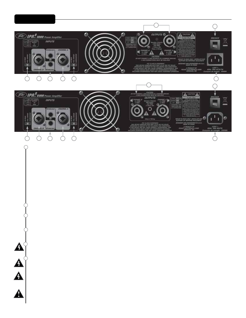
CHANNEL MODE SWITCH:
HIGH PASS
This position is used to activate the HIGH PASS filter for the corresponding channel. This filter will limit the frequencies sent to the associated
amplifier channel to frequencies above 100 Hz. In situations where separate subwoofer cabinets are being used, this position would indicate
connecting the mid-high frequency speaker cabinet to the channel associated with the HIGH PASS switch.
FULL RANGE
As the name implies, the Full Range position on this switch allows all frequencies to pass to the amplifier. Normally used when connecting a
full range speaker enclosure to the amplifier's output.
SUBWOOFER
This position is used to activate the LOW PASS filter for the corresponding channel. This filter will limit the frequencies sent to the associated
amplifier channel to frequencies below 100 Hz. In situations where separate subwoofer cabinets are being used, this position would indicate
connecting the subwoofer speaker cabinet to the channel associated with the Subwoofer switch.
THRU/OUT JACKS
This 1/4” (6.3mm) jack supplies parallel output signals from the associated channel for patching to this amplifier and/or additional power amplifier inputs.
CONNECTING INPUTS
This 1/4” (6.3mm) jack is a parallel connection to the input connector for patching to this amplifier and/or additional power amplifier inputs. A TRS plug must
be used to maintain a balanced connection.
CONNECTING OUTPUTS
All models have one two-pole twist lock and 1/4” (6.3mm) phone plug combination connector per channel. All four speaker connection wires
must be isolated from each other.
CIRCUIT BREAKER
In the unlikely event of operating conditions that may potentially damage the amplifier, the circuit breaker may trip. After inspecting the cables and
connections, the amplifier can be reset. If the circuit breaker trips a second time, contact the local Peavey authorized service center.
AC POWER INLET:
This is the receptacle for an IEC line cord, which provides AC power to the unit. Connect the line cord to this connector to provide power to the
unit. Damage to the equipment may result if improper line voltage is used. (See line voltage marking on unit).
Never break off the ground pin on any equipment. It is provided for your safety. If the outlet used does not have a ground pin, a suitable
grounding adapter should be used and the third wire should be grounded properly. To prevent the risk of shock or fire hazard, always make sure
that the amplifier and all associated equipment is properly grounded.
NOTE: FOR U.K. ONLY
As the colors of the wires in the mains lead of this apparatus may not correspond with the colored markings identifying the terminals in your plug,
proceed as follows: (1) The wire which is colored green and yellow must be connected to the terminal which is marked by the letter E, or by the Earth
symbol, or colored green or green and yellow. (2) The wire which is colored blue must be connected to the terminal which is marked with the letter
N, or the color black. (3) The wire which is colored brown must be connected to the terminal which is marked with the letter L, or the color red.
Rear Panel
IPR2
™
3000
15
14
12
12
11
10
11
12
13
14
15
10
10
13
IPR2
™
2000
15
14
12
12
11
10
10
13