Dmc2700udm new prod uc t, Electrical characteristics n-channel – q, Electrical characteristics p-channel – q – Diodes DMC2700UDM User Manual
Page 3: Dmc2700udm, A product line of diodes incorporated
DMC2700UDM
Datasheet Number: DS35360 Rev. 1 - 2
3 of 9
June 2011
© Diodes Incorporated
DMC2700UDM
NEW PROD
UC
T
A Product Line of
Diodes Incorporated
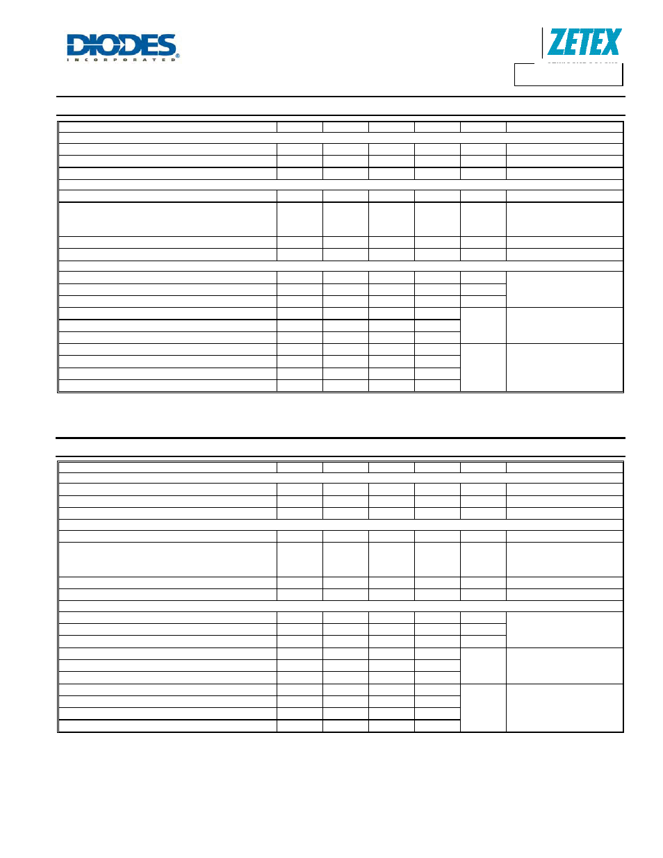
Electrical Characteristics N-CHANNEL – Q
1
@T
A
= 25°C unless otherwise specified
Characteristic Symbol
Min
Typ
Max
Unit
Test
Condition
OFF CHARACTERISTICS (Note 5)
Drain-Source Breakdown Voltage
BV
DSS
20
⎯
⎯
V
V
GS
= 0V, I
D
= 250
μA
Zero Gate Voltage Drain Current
I
DSS
⎯
⎯
100 nA
V
DS
= 20V, V
GS
= 0V
Gate-Source Leakage
I
GSS
⎯
⎯
± 1.0
μA
V
GS
= ±4.5V, V
DS
= 0V
ON CHARACTERISTICS (Note 5)
Gate Threshold Voltage
V
GS(th)
0.5
⎯
1.0 V
V
DS
= V
GS
, I
D
= 250
μA
Static Drain-Source On-Resistance
R
DS (ON)
⎯
⎯
⎯
0.3
0.4
0.5
0.4
0.5
0.7
Ω
V
GS
= 4.5V, I
D
= 600mA
V
GS
= 2.5V, I
D
= 500mA
V
GS
= 1.8V, I
D
= 350mA
Forward Transfer Admittance
|Y
fs
|
⎯
1.4
⎯
S
V
DS
=10V, I
D
= 400mA
Diode Forward Voltage (Note 5)
V
SD
⎯
0.7 1.2 V
V
GS
= 0V, I
S
= 150mA
DYNAMIC CHARACTERISTICS
Input Capacitance
C
iss
⎯
60.67
⎯
pF
V
DS
= 16V, V
GS
= 0V
f = 1.0MHz
Output Capacitance
C
oss
⎯
9.68
⎯
pF
Reverse Transfer Capacitance
C
rss
⎯
5.37
⎯
pF
Total Gate Charge
Q
g
⎯
736.6
⎯
pC
V
GS
= 4.5V, V
DS
= 10V,
I
D
= 250mA
Gate-Source Charge
Q
gs
⎯
93.6
⎯
Gate-Drain Charge
Q
gd
⎯
116.6
⎯
Turn-On Delay Time
t
d(on)
⎯
5.1
⎯
ns
V
DD
= 10V, V
GS
= 4.5V,
R
L
= 47
Ω, R
G
= 10
Ω,
I
D
= 200mA
Turn-On Rise Time
t
r
⎯
7.4
⎯
Turn-Off Delay Time
t
d(off)
⎯
26.7
⎯
Turn-Off Fall Time
t
f
⎯
12.3
⎯
Electrical Characteristics P-CHANNEL – Q
2
@T
A
= 25°C unless otherwise specified
Characteristic Symbol
Min
Typ
Max
Unit
Test
Condition
OFF CHARACTERISTICS (Note 5)
Drain-Source Breakdown Voltage
BV
DSS
-20
⎯
⎯
V
V
GS
= 0V, I
D
= -250
μA
Zero Gate Voltage Drain Current
I
DSS
⎯
⎯
-100 nA
V
DS
= -20V, V
GS
= 0V
Gate-Source Leakage
I
GSS
⎯
⎯
± 1.0
μA
V
GS
= ±4.5V, V
DS
= 0V
ON CHARACTERISTICS (Note 5)
Gate Threshold Voltage
V
GS(th)
-0.5
⎯
-1.0 V
V
DS
= V
GS
, I
D
= -250
μA
Static Drain-Source On-Resistance
R
DS (ON)
⎯
0.5
0.7
1.0
0.7
0.9
1.3
Ω
V
GS
= -4.5V, I
D
= -430mA
V
GS
= -2.5V, I
D
= -300mA
V
GS
= -1.8V, I
D
= -150mA
Forward Transfer Admittance
|Y
fs
|
⎯
-0.9
⎯
S
V
DS
=10V, I
D
= -250mA
Diode Forward Voltage (Note 5)
V
SD
⎯
-0.8 -1.2 V
V
GS
= 0V, I
S
= -150mA
DYNAMIC CHARACTERISTICS
Input Capacitance
C
iss
⎯
59.76
⎯
pF
V
DS
= -16V, V
GS
= 0V
f = 1.0MHz
Output Capacitance
C
oss
⎯
12.07
⎯
pF
Reverse Transfer Capacitance
C
rss
⎯
6.36
⎯
pF
Total Gate Charge
Q
g
⎯
622.4
⎯
pC
V
GS
= -4.5V, V
DS
= -10V,
I
D
= -250mA
Gate-Source Charge
Q
gs
⎯
100.3
⎯
Gate-Drain Charge
Q
gd
⎯
132.2
⎯
Turn-On Delay Time
t
d(on)
⎯
5.1
⎯
ns
V
DD
= -10V, V
GS
= -4.5V,
R
L
= 47
Ω, R
G
= 10
Ω,
I
D
= -200mA
Turn-On Rise Time
t
r
⎯
8.1
⎯
Turn-Off Delay Time
t
d(off)
⎯
28.4
⎯
Turn-Off Fall Time
t
f
⎯
20.7
⎯
Notes: 5. Short duration pulse test used to minimize self-heating effect.