Parts replacement (continued) – Nexen DPC-13T 962200 User Manual
Page 13
13
FORM NO. L-20093-L-1209
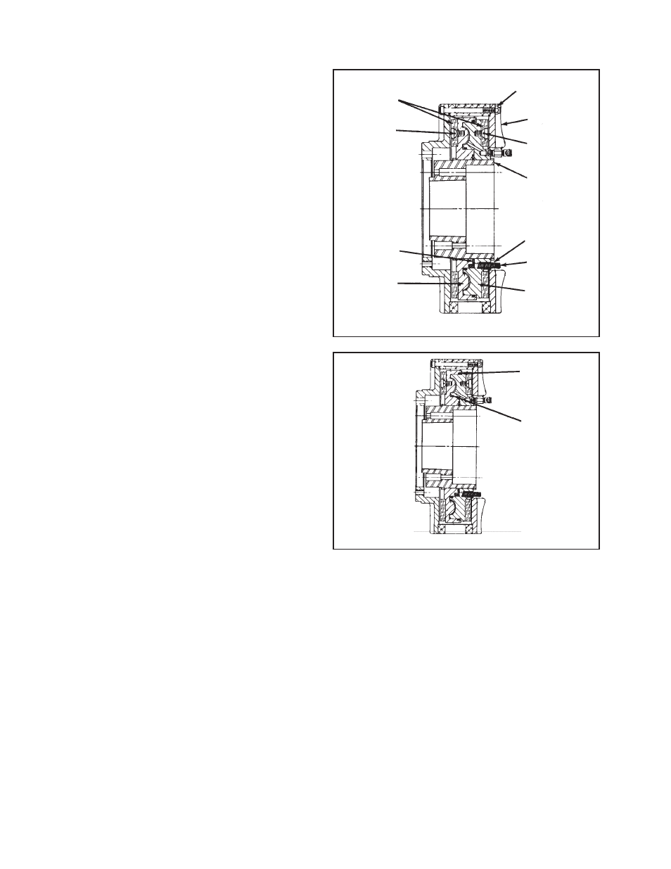
O-RINGS (ITEMS 8 & 9)
Refer to Figure 10.
NOTE: Replace O-Rings (Items 8 & 9) if there are noticeable
air leaks or a loss of torque.
1. Proceed with Steps 1 through 7 for Friction Facing
Replacement.
2. Remove old O-Rings (Items 8 & 9) and clean O-Ring
contact surfaces with fresh safety solvent.
3. Lubricate new O-Rings (Items 8 & 9), and O-Ring
contact surfaces with fresh O-Ring lubricant.
4. Install new O-Rings (Items 8 & 9).
5. Reverse Step 1 to reassemble the DPC Clutch, noting
the chalk alignment marks, and tighten all screws to the
recommended torque (See Table 9).
FIGURE 10
9
8
PARTS REPLACEMENT (continued)
NOTE: On some models of the DPC-13T and DPC-15T
the Machine Screws (Item 11) are assembled
with a green anaerobic thread locking
compound. If removal is difficult, strike the
end of the screwdriver with a hammer to break
the crystalline structure of this thread locking
compound before attempting to remove the
machine screws. The Machine Screws (Item
11) furnished with the new Friction Facings
have a locking patch and do not require the
use of a thread locking compound.
9. Reverse Steps 1 through 7 to reassemble the DPC
Clutch; noting all chalk alignment marks, and tighten all
screws to the recommended torque (See Table 9).
FIGURE 9
4
20
7
11
1
14
13
2
3
10
11